1. Accessing More I/O
So far the examples have shown how to access the GPIO pins on the BeagleBone Black’s
P9 header and through the __R30 register. Below shows how more GPIO pins
can be accessed.
The following are resources used in this chapter.
1.1. Editing /boot/uEnv.txt to Access the P8 Header on the Black
Problem
When I try to configure some pins on the P8 header of the Black I get an error.
bone$ config-pin P8_28 pruout
ERROR: open() for /sys/devices/platform/ocp/ocp:P8_28_pinmux/state failed, No such file or directory
Solution
On the images for the BeagleBone Black, the HDMI display driver is enabled by
default and uses many of the P8 pins. If you are not using
HDMI video (or the HDI audio, or even the eMMC) you can disable it by editing
/boot/uEnv.txt
Open /boot/uEnv.txt and scroll down aways until you see:
###Disable auto loading of virtual capes (emmc/video/wireless/adc)
#disable_uboot_overlay_emmc=1
disable_uboot_overlay_video=1
#disable_uboot_overlay_audio=1
Uncomment the lines that correspond to the devices you want to disable and free up their pins.
|
Tip
|
P8 Header Table shows what pins are allocated for what. |
Save the file and reboot. You now have access to the P8 pins.
1.2. Accessing gpio
Problem
I’ve used up all the GPIO in __R30, where can I get more?
Solution
So far we have focused on using PRU 0. Mapping bit positions to pin names PRU shows that PRU 0 can access ten GPIO pins on the BeagleBone Black. If you use PRU 1 you can get to an additional 14 pins (if they aren’t in use for other things.)
What if you need even more GPIO pins? You can access any GPIO pin by going through the Open-Core Protocol (OCP) port.
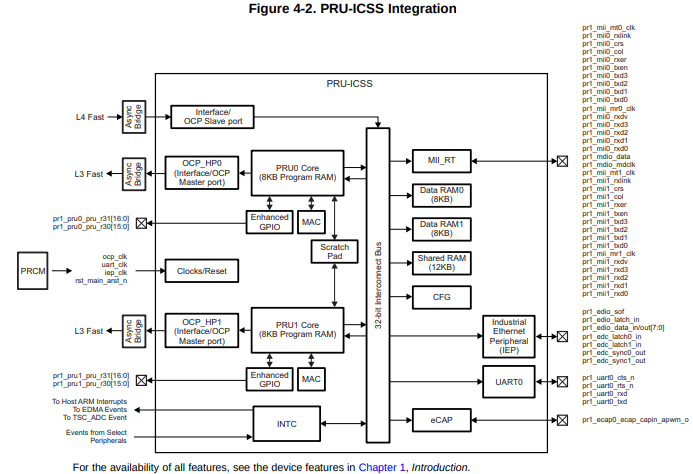
The figure above shows we’ve been using the Enhanced GPIO interface when using
__R30, but it also shows you can use the OCP. You get access to many more
GPIO pins, but it’s a slower access.
  1
2
3
4
5
6
7
8
9
10
11
12
13
14
15
16
17
18
19
20
21
22
23

  // This code accesses GPIO without using R30 and R31
#include <stdint.h>
#include <pru_cfg.h>
#include "resource_table_empty.h"
#include "prugpio.h"

#define P9_11   (0x1<<30)           // Bit position tied to P9_11 on Black
#define P2_05   (0x1<<30)           // Bit position tied to P2_05 on Pocket

volatile register uint32_t __R30;
volatile register uint32_t __R31;

void main(void)
{
    uint32_t *gpio0 = (uint32_t *)GPIO0;

    while(1) {
        gpio0[GPIO_SETDATAOUT]   = P9_11;
        __delay_cycles(100000000);
        gpio0[GPIO_CLEARDATAOUT] = P9_11;
        __delay_cycles(100000000);
    }
}
This code will toggle P9_11 on and off. Here’s the setup file.
  1
2
3
4
5
6
7
8
9
10
11
12
13
14
15
16
17
18
19
20
21
22
23
24
25
26
27
28

  #!/bin/bash

export TARGET=gpio.pru0
echo TARGET=$TARGET

# Configure the PRU pins based on which Beagle is running
machine=$(awk '{print $NF}' /proc/device-tree/model)
echo -n $machine
if [ $machine = "Black" ]; then
    echo " Found"
    pins="P9_11"
elif [ $machine = "Blue" ]; then
    echo " Found"
    pins=""
elif [ $machine = "PocketBeagle" ]; then
    echo " Found"
    pins="P2_05"
else
    echo " Not Found"
    pins=""
fi

for pin in $pins
do
    echo $pin
    config-pin $pin gpio
    config-pin -q $pin
done
Notice in the code config-pin set P9_11 to gpio, not pruout. This is because
are are using the OCP interface to the pin, not the usual PRU interface.
Set your exports and make.
bone$ source setup.sh
TARGET=gpio.pru0
...
bone$ make
/var/lib/cloud9/common/Makefile:29: MODEL=TI_AM335x_BeagleBone_Black,TARGET=gpio.pru0
-    Stopping PRU 0
-   copying firmware file /tmp/cloud9-examples/gpio.pru0.out to /lib/firmware/am335x-pru0-fw
write_init_pins.sh
-    Starting PRU 0
MODEL   = TI_AM335x_BeagleBone_Black
PROC    = pru
PRUN    = 0
PRU_DIR = /sys/class/remoteproc/remoteproc1
Discussion
When you run the code you see P9_11 toggling on and off. Let’s go through
the code line-by-line to see what’s happening.
| Line | Explanation |
|---|---|
2-5 |
Standard includes |
5 |
The AM335x has four 32-bit GPIO ports. Lines 55-58 of You can also run
|
5 |
Line 103 of |
5 |
Line 104 of |
5 |
Using this offset of line 105 of |
7,8 |
This shifts |
15 |
Here we initialize |
18 |
|
19 |
Wait 100,000,000 cycles, which is 0.5 seconds. |
20 |
This is line 18, but the output bit is set to 0 where 1’s are written. |
How fast can it go?
This approach to GPIO goes through the slower OCP interface. If you set __delay_cycles(0) you can see how fast it is.
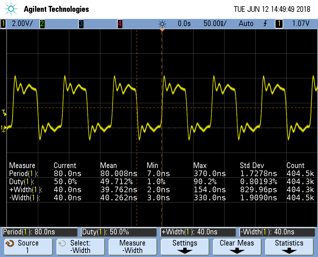
The period is 80ns which is 12.MHz. That’s about one forth the speed of the
__R30 method, but still not bad.
If you are using an oscilloscope, look closely and you’ll see the following.
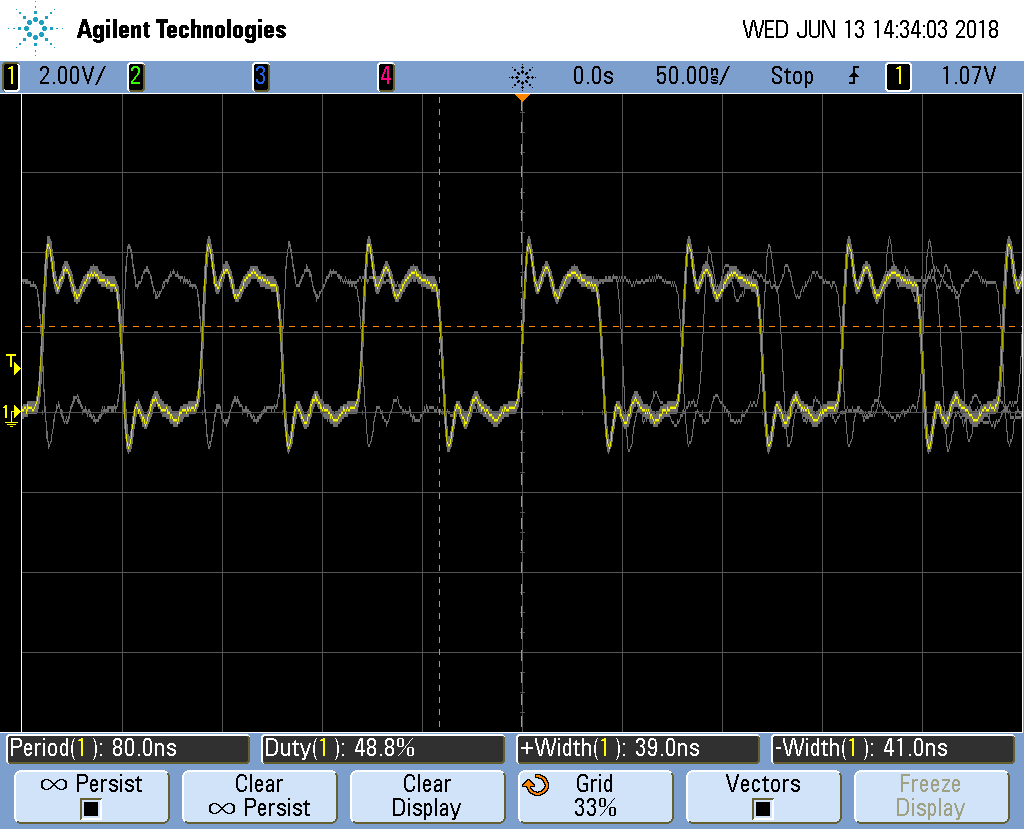
The PRU is still as solid as before in it’s timing, but now it’s going through the OCP interface. This interface is shared with other parts of the system, therefore the sometimes the PRU must wait for the other parts to finish. When this happens the pulse width is a bit longer than usual thus adding jitter to the output.
For many applications a few nanoseconds of jitter is unimportant and this
GPIO interface can be used. If your application needs better timing,
use the __R30 interface.
1.3. Configuring for UIO Instead of RemoteProc
Problem
You have some legacy PRU code that uses UIO instead of remoteproc and you want to switch to UIO.
Solution
Edit /boot/uEnt.txt and search for uio. I find
###pru_uio (4.4.x-ti, 4.9.x-ti, 4.14.x-ti & mainline/bone kernel)
uboot_overlay_pru=/lib/firmware/AM335X-PRU-UIO-00A0.dtbo
Uncomment the uboot line. Look for other lines with
uboot_overlay_pru= and be sure they are commented out.
Reboot your Bone.
bone$ sudo reboot
Check that UIO is running.
bone$ lsmod | grep uio
uio_pruss              16384  0
uio_pdrv_genirq        16384  0
uio                    20480  2 uio_pruss,uio_pdrv_genirq
You are now ready to run the legacy PRU code.
1.4. Converting pasm Assembly Code to clpru
Problem
You have some legacy assembly code written in pasm and it won’t assemble with clpru.
Solution
Generally there is a simple mapping from pasm to clpru. pasm vs. clpru notes what needs to be changed. I have a less complete version on my eLinux.org site.
Discussion
The clpru assembly can be found in PRU Assembly Language Tools.