1. Building Blocks - Applications
Here are some examples that use the basic PRU building blocks.
The following are resources used in this chapter.
These examples are based on other’s examples. The copyright headers have been removed from the code for claity and reproduced at the end of the chaper.
1.1. Memory Allocation
Problem
I want to control where my variables are stored in memory.
Solution
Each PRU has is own 8KB of data memory (Data Mem0 and Mem1) and 12KB of shared memory (Shared RAM) as shown in PRU Block Diagram.
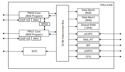
Each PRU accesses it’s own DRAM starting at location 0x0000_0000. Each PRU can also access the other PRU’s DRAM starting at 0x0000_2000. Both PRUs access the shared RAM at 0x0001_0000. The compiler can control where each of these memories variables are stored.
shared.pro0.c - Examples of Using Different Memory Locations shows how to allocate seven variable in six different locations.
Discussion
Here’s the line-by-line
| Line | Explanation |
|---|---|
7 |
|
8, 9 |
These are like the previous line except for the DMEM sections. |
16 |
Variables declared outside of |
17 |
Adding |
18, 19 |
These are stored in the PRU’s local RAM. |
20, 21 |
These lines are for storing in the |
28-31 |
All the previous examples direct the compiler to an area in memory and the compilers figures out what to put where. With these lines we specify the exact location. Here are start with the PRU_DRAM starting address and add 0x200 to it to avoid the stack and the heap. The advantage of this technique is you can easily share these variables between the ARM and the two PRUs. |
36, 37 |
Variable declared inside |
|
Caution
|
Using the technique of line 28-31 you can put variables anywhere, even where the compiler has put them. Be careful, it’s easy to overwrite what the compiler has done |
Compile and run the program.
bone$ source shared_setup.sh
TARGET=shared.pru0
Black Found
P9_31
Current mode for P9_31 is:     pruout
Current mode for P9_31 is:     pruout
P9_29
Current mode for P9_29 is:     pruout
Current mode for P9_29 is:     pruout
P9_30
Current mode for P9_30 is:     pruout
Current mode for P9_30 is:     pruout
P9_28
Current mode for P9_28 is:     pruout
Current mode for P9_28 is:     pruout
bone$ make
/var/lib/cloud9/common/Makefile:29: MODEL=TI_AM335x_BeagleBone_Black,TARGET=shared.pru0
-    Stopping PRU 0
-   copying firmware file /tmp/cloud9-examples/shared.pru0.out to /lib/firmware/am335x-pru0-fw
write_init_pins.sh
-    Starting PRU 0
MODEL   = TI_AM335x_BeagleBone_Black
PROC    = pru
PRUN    = 0
PRU_DIR = /sys/class/remoteproc/remoteproc1
Now check the symbol table to see where things are allocated.
bone $ grep shared /tmp/cloud9-examples/shared.pru0.map
....
1     0000011c  shared_0
2     00010000  shared_1
1     00000000  shared_2
1     00002000  shared_3
1     00000118  shared_4
1     00000120  shared_5
We see, shared_0 had no directives and was places in the heap that is 0x100
to 0x1ff. shared_1 was directed to go to the SHAREDMEM, shared_2 to
the start of the local DRAM (which is also the top of the stack). shared_3
was placed in the DRAM of PRU 1, shared_4 was placed in the .bss section,
which is in the heap. Finally shared_5 is a pointer to where the value
is stored.
Where are shared_6 and shared_7? They are declared inside main() and are
therefore placed on the stack at run time. The shared.map file shows the
compile time allocations. We have to look in the memory itself to see what
happen at run time.
Let’s fire up prudebug
(prudebug - A Simple Debugger for the PRU)
to see where things are.
bone$ sudo ./prudebug
PRU Debugger v0.25
(C) Copyright 2011, 2013 by Arctica Technologies.  All rights reserved.
Written by Steven Anderson

Using /dev/mem device.
Processor type      AM335x
PRUSS memory address    0x4a300000
PRUSS memory length 0x00080000

         offsets below are in 32-bit byte addresses (not ARM byte addresses)
         PRU            Instruction    Data         Ctrl
         0              0x00034000     0x00000000   0x00022000
         1              0x00038000     0x00002000   0x00024000

PRU0> d 0
Absolute addr = 0x0000, offset = 0x0000, Len = 16
[0x0000] 0x0000feed 0x00000000 0x00000000 0x00000000
[0x0010] 0x00000000 0x00000000 0x00000000 0x00000000
[0x0020] 0x00000000 0x00000000 0x00000000 0x00000000
[0x0030] 0x00000000 0x00000000 0x00000000 0x00000000
The value of shared_2 is in memory location 0.
PRU0> dd 0x100
Absolute addr = 0x0100, offset = 0x0000, Len = 16
[0x0100] 0x00000000 0x00000001 0x00000000 0x00000000
[0x0110] 0x00000000 0x00000000 0x0000beed 0x0000feef
[0x0120] 0x00000200 0x3ec71de3 0x1a013e1a 0xbf2a01a0
[0x0130] 0x111110b0 0x3f811111 0x55555555 0xbfc55555
There are shared_0 and shared_4 in the heap, but where is shared_6 and
shared_7? They are supposed to be on the stack that starts at 0.
PRU0> dd 0xc0
Absolute addr = 0x00c0, offset = 0x0000, Len = 16
[0x00c0] 0x00000000 0x00000000 0x00000000 0x00000000
[0x00d0] 0x00000000 0x00000000 0x00000000 0x00000000
[0x00e0] 0x00000000 0x00000000 0x00000000 0x00000000
[0x00f0] 0x00000000 0x00000000 0x00004321 0x00009876
There they are; the stack grows from the top. (The heap grows from the bottom.)
PRU0> dd 0x2000
Absolute addr = 0x2000, offset = 0x0000, Len = 16
[0x2000] 0x0000deed 0x00000001 0x00000000 0x557fcfb5
[0x2010] 0xce97bd0f 0x6afb2c8f 0xc7f35df4 0x5afb6dcb
[0x2020] 0x8dec3da3 0xe39a6756 0x642cb8b8 0xcb6952c0
[0x2030] 0x2f22ebda 0x548d97c5 0x9241786f 0x72dfeb86
And there is PRU 1’s memory with shared_3. And finally the shared memory.
PRU0> dd 0x10000
Absolute addr = 0x10000, offset = 0x0000, Len = 16
[0x10000] 0xdeadbeef 0x0000feed 0x00000000 0x68c44f8b
[0x10010] 0xc372ba7e 0x2ffa993b 0x11c66da5 0xfbf6c5d7
[0x10020] 0x5ada3fcf 0x4a5d0712 0x48576fb7 0x1004796b
[0x10030] 0x2267ebc6 0xa2793aa1 0x100d34dc 0x9ca06d4a
The compiler offers great control over where variables are stored. Just be sure if you are hand picking where things are put, not to put them in places used by the compiler.
1.2. Auto Initialization of built-in LED Triggers
Problem
I see the built-in LEDs blink to their own patterns. How do I turn this off? Can this be automated?
Solution
Each built-in LED has a default action (trigger) when the Bone boots up.
This is controlled by /sys/class/leds.
bone$ cd /sys/class/leds
bone$ ls
beaglebone:green:usr0  beaglebone:green:usr2
beaglebone:green:usr1  beaglebone:green:usr3
Here you see a directory for each of the LEDs. Let’s pick USR1.
bone$ cd beaglebone\:green\:usr1
bone$ ls
brightness  device  max_brightness  power  subsystem  trigger  uevent
bone$ cat trigger
none usb-gadget usb-host rfkill-any rfkill-none kbd-scrolllock kbd-numlock
kbd-capslock kbd-kanalock kbd-shiftlock kbd-altgrlock kbd-ctrllock kbd-altlock
kbd-shiftllock kbd-shiftrlock kbd-ctrlllock kbd-ctrlrlock [mmc0] timer
oneshot disk-activity disk-read disk-write ide-disk mtd nand-disk heartbeat
backlight gpio cpu cpu0 activity default-on panic netdev phy0rx phy0tx
phy0assoc phy0radio rfkill0
Notice [mmc0] is in brackets. This means it’s the current trigger; it flashes
when the built-in flash memory is in use. You can turn this off using:
bone$ echo none > trigger
bone$ cat trigger
[none] usb-gadget usb-host rfkill-any rfkill-none kbd-scrolllock kbd-numlock
kbd-capslock kbd-kanalock kbd-shiftlock kbd-altgrlock kbd-ctrllock kbd-altlock
kbd-shiftllock kbd-shiftrlock kbd-ctrlllock kbd-ctrlrlock mmc0 timer
oneshot disk-activity disk-read disk-write ide-disk mtd nand-disk heartbeat
backlight gpio cpu cpu0 activity default-on panic netdev phy0rx phy0tx
phy0assoc phy0radio rfkill0
Now it is no longer flashing.
How can this be automated so when code is run that needs the trigger off, it’s turned off automatically? Here’s a trick. Include the following in your code.
  1
2
3
4
5

  #pragma DATA_SECTION(init_pins, ".init_pins")
#pragma RETAIN(init_pins)
const char init_pins[] =
        "/sys/class/leds/beaglebone:green:usr3/trigger\0none\0" \
        "\0\0";
Lines 3 and 4 declare the array init_pins to have an entry which is the path
to trigger and the value that should be 'echoed' into it. Both are NULL
terminated. Line 1 says to put this in a section called .init_pins and
line 2 says to RETAIN it. That is don’t throw it away if it appears to be
unused.
Discussion
The above code stores this array in the .out file thats created, but that’s not
enough. You need to run write_init_pins.sh on the .out file to make
the code work. Fortunately the Makefile always runs it.
  1
2
3
4
5
6
7
8
9

  #!/bin/bash
init_pins=$(readelf -x .init_pins $1 | grep 0x000 | cut -d' ' -f4-7 | xxd -r -p | tr '\0' '\n' | paste - -)
while read -a line; do
    if [ ${#line[@]} == 2 ]; then
        echo writing \"${line[1]}\" to \"${line[0]}\"
        echo ${line[1]} > ${line[0]}
        sleep 0.1
    fi
done <<< "$init_pins"
The readelf command extracts the path and value from the .out file.
bone$ readelf -x .init_pins /tmp/pru0-gen/shared.out

Hex dump of section '.init_pins':
  0x000000c0 2f737973 2f636c61 73732f6c 6564732f /sys/class/leds/
  0x000000d0 62656167 6c65626f 6e653a67 7265656e beaglebone:green
  0x000000e0 3a757372 332f7472 69676765 72006e6f :usr3/trigger.no
  0x000000f0 6e650000 0000                       ne....
The rest of the command formats it. Finally line 6 echos the none into
the path.
This can be generalized to initialize other things. The point is, the .out
file contains everything needed to run the executable.
1.3. PWM Generator
One of the simplest things a PRU can to is generate a simple signal starting with a single channel PWM that has a fixed frequency and duty cycle and ending with a multi channel PWM that the ARM can change the frequency and duty cycle on the fly.
Problem
I want to generate a PWM signal that has a fixed frequency and duty cycle.
Solution
The solution is fairly easy, but be sure to check the Discussion section for details on making it work.
pwm1.pru0.c shows the code.
|
Warning
|
This code is for the BeagleBone Black. See |
  1
2
3
4
5
6
7
8
9
10
11
12
13
14
15
16
17
18
19
20
21
22

  #include <stdint.h>
#include <pru_cfg.h>
#include "resource_table_empty.h"
#include "prugpio.h"

volatile register uint32_t __R30;
volatile register uint32_t __R31;

void main(void)
{
    uint32_t gpio = P1_31;  // Select which pin to toggle.;

    /* Clear SYSCFG[STANDBY_INIT] to enable OCP master port */
    CT_CFG.SYSCFG_bit.STANDBY_INIT = 0;

    while(1) {
        __R30 |= gpio;      // Set the GPIO pin to 1
        __delay_cycles(1000);
        __R30 &= ~gpio;     // Clear the GPIO pin
        __delay_cycles(1000);
    }
}
To run this code you need to configure the pin muxes to output the PRU. If you are on the Black run
bone$ config-pin P9_31 pruoutOn the Pocket run
bone$ config-pin P1_36 pruout|
Note
|
See Configuring pins on the AI via device trees for configuring pins on the AI. |
Then, tell Makefile which PRU you are compiling for and what your target file is
bone$ export TARGET=pwm1.pru0Now you are ready to compile
bone$ make
/var/lib/cloud9/common/Makefile:29: MODEL=TI_AM335x_BeagleBone_Black,TARGET=pwm1.pru0
-    Stopping PRU 0
-   copying firmware file /tmp/cloud9-examples/pwm1.pru0.out to /lib/firmware/am335x-pru0-fw
write_init_pins.sh
-    Starting PRU 0
MODEL   = TI_AM335x_BeagleBone_Black
PROC    = pru
PRUN    = 0
PRU_DIR = /sys/class/remoteproc/remoteproc1
Now attach an LED (or oscilloscope) to P9_31 on the Black or P1.36 on the Pocket. You should see a squarewave.
Discussion
Since this is our first example we’ll discuss the many parts in detail.
pwm1.pru0.c
Line-by-line of pwm1.pru0.c is a line-by-line expanation of the c code.
| Line | Explanation |
|---|---|
1 |
Standard c-header include |
2 |
Include for the PRU. The compiler knows where to find this since the |
3 |
The file |
4 |
This include has addresses for the GPIO ports and some bit positions for some of the headers. |
Here’s what’s in resource_table_empty.h
  1
2
3
4
5
6
7
8
9
10
11
12
13
14
15
16
17
18
19
20
21
22
23
24
25
26
27
28
29
30
31
32
33
34
35
36
37
38

  /*
 *  ======== resource_table_empty.h ========
 *
 *  Define the resource table entries for all PRU cores. This will be
 *  incorporated into corresponding base images, and used by the remoteproc
 *  on the host-side to allocated/reserve resources.  Note the remoteproc
 *  driver requires that all PRU firmware be built with a resource table.
 *
 *  This file contains an empty resource table.  It can be used either as:
 *
 *        1) A template, or
 *        2) As-is if a PRU application does not need to configure PRU_INTC
 *                  or interact with the rpmsg driver
 *
 */

#ifndef _RSC_TABLE_PRU_H_
#define _RSC_TABLE_PRU_H_

#include <stddef.h>
#include <rsc_types.h>

struct my_resource_table {
    struct resource_table base;

    uint32_t offset[1]; /* Should match 'num' in actual definition */
};

#pragma DATA_SECTION(pru_remoteproc_ResourceTable, ".resource_table")
#pragma RETAIN(pru_remoteproc_ResourceTable)
struct my_resource_table pru_remoteproc_ResourceTable = {
    1,  /* we're the first version that implements this */
    0,  /* number of entries in the table */
    0, 0,   /* reserved, must be zero */
    0,  /* offset[0] */
};

#endif /* _RSC_TABLE_PRU_H_ */
| Line | Explanation |
|---|---|
6-7 |
|
11 |
This line selects which GPIO pin to toggle. The table below shows which bits in |
14 |
|
Bit 0 is the LSB.
| PRU | Bit | Black pin | Pocket pin |
|---|---|---|---|
0 |
0 |
P9_31 |
P1.36 |
0 |
1 |
P9_29 |
P1.33 |
0 |
2 |
P9_30 |
P2.32 |
0 |
3 |
P9_28 |
P2.30 |
0 |
4 |
P9_42b |
P1.31 |
0 |
5 |
P9_27 |
P2.34 |
0 |
6 |
P9_41b |
P2.28 |
0 |
7 |
P9_25 |
P1.29 |
0 |
14 |
P8_12(out) P8_16(in) |
P2.24 |
0 |
15 |
P8_11(out) P8_15(in) |
P2.33 |
--- |
--- |
--------- |
----- |
1 |
0 |
P8_45 |
|
1 |
1 |
P8_46 |
|
1 |
2 |
P8_43 |
|
1 |
3 |
P8_44 |
|
1 |
4 |
P8_41 |
|
1 |
5 |
P8_42 |
|
1 |
6 |
P8_39 |
|
1 |
7 |
P8_40 |
|
1 |
8 |
P8_27 |
P2.35 |
1 |
9 |
P8_29 |
P2.01 |
1 |
10 |
P8_28 |
P1.35 |
1 |
11 |
P8_30 |
P1.04 |
1 |
12 |
P8_21 |
|
1 |
13 |
P8_20 |
|
1 |
14 |
P1.32 |
|
1 |
15 |
P1.30 |
|
1 |
16 |
P9_26(in) |
|
Note
|
See Configuring pins on the AI via device trees for all the PRU pins on the AI. |
Since we are running on PRU 0, and we’re using 0x0001, that is bit 0,
we’ll be toggling P9_31.
| Line | Explanation |
|---|---|
17 |
Here is where the action is. This line reads |
18 |
|
19 |
This is like line 17, but |
|
Tip
|
You can read more about instrinsics in section 5.11 of the (PRU Optimizing C/C++ Compiler, v2.2, User’s Guide.) |
When you run this code and look at the output you will see something like the following figure.
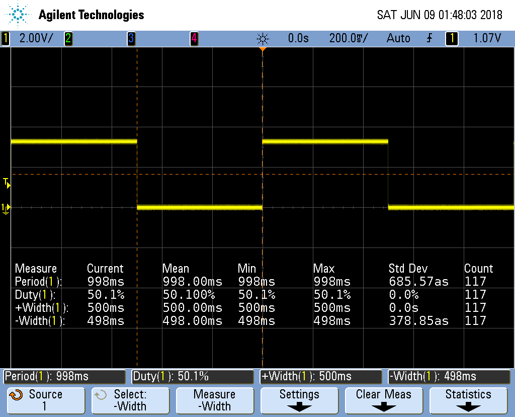
Notice the on time (+Width(1)) is 500ms, just as we predicted. The off time is 498ms, which is only 2ms off from our prediction. The standard deviation is 0, or only 380as, which is 380 * 10-18!.
You can see how fast the PRU can run by setting both of the __delay_cycles to 0. This results in the next figure.
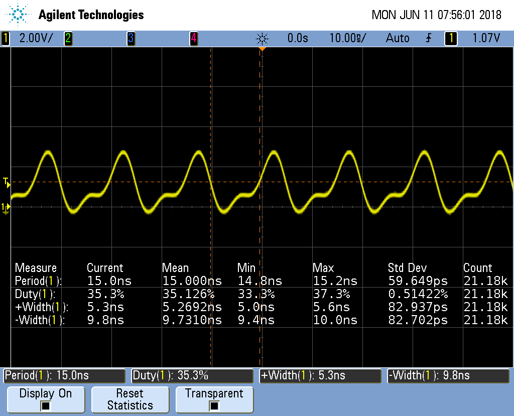
Notice the period is 15ns which gives us a frequency of about 67MHz. At this high frequency the breadboard that I’m using distorts the waveform so it’s no longer a squarewave. The on time is 5.3ns and the off time is 9.8ns. That means __R30 |= gpio took only one 5ns cycle and __R30 &= ~gpio also only took one cycle, but there is also an extra cycle needed for the loop. This means the compiler was able to implement the while loop in just three 5ns instructions! Not bad.
We want a square wave, so we need to add a delay to correct for the delay of looping back.
Here’s the code that does just that.
  1
2
3
4
5
6
7
8
9
10
11
12
13
14
15
16
17
18
19
20
21
22

  #include <stdint.h>
#include <pru_cfg.h>
#include "resource_table_empty.h"
#include "prugpio.h"

volatile register uint32_t __R30;
volatile register uint32_t __R31;

void main(void)
{
    uint32_t gpio = P1_31;  // Select which pin to toggle.;

    /* Clear SYSCFG[STANDBY_INIT] to enable OCP master port */
    CT_CFG.SYSCFG_bit.STANDBY_INIT = 0;

    while (1) {
        __R30 |= gpio;      // Set the GPIO pin to 1
        __delay_cycles(1001);   // Delay one cycle to correct for loop time
        __R30 &= ~gpio;     // Clear the GPIO pin
        __delay_cycles(1000);
    }
}
The output now looks like:
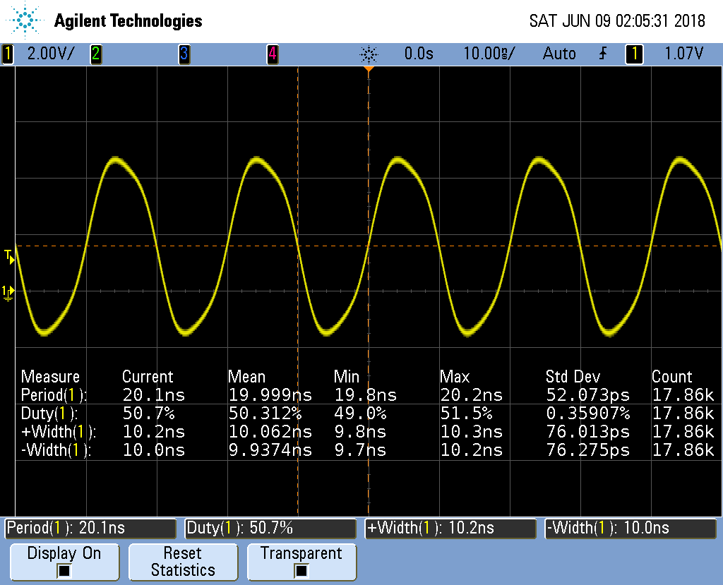
It’s not hard to adjust the two __delay_cycles to get the desired frequency and duty cycle.
1.4. Controlling the PWM Frequency
Problem
You would like to control the frequency and duty cycle of the PWM without recompiling.
Solution
Have the PRU read the on and off times from a shared memory location. Each PRU has is own 8KB of data memory (DRAM) and 12KB of shared memory (SHAREDMEM) that the ARM processor can also access. See PRU Block Diagram.
The DRAM 0 address is 0x0000 for PRU 0. The same DRAM appears at address 0x4A300000 as seen from the ARM processor.
|
Tip
|
See page 184 of the AM335x Technical Reference Manual. |
We take the previous PRU code and add the lines
  1
2

  #define PRU0_DRAM       0x00000         // Offset to DRAM
volatile unsigned int *pru0_dram = PRU0_DRAM;
to define a pointer to the DRAM.
|
Note
|
The |
Later in the code we use
  1
2

      pru0_dram[ch] = on[ch];         // Copy to DRAM0 so the ARM can change it
    pru0_dram[ch+MAXCH] = off[ch];  // Copy after the on array
to write the on and off times to the DRAM. Then inside the while loop we use
  1
2

      onCount[ch] = pru0_dram[2*ch];      // Read from DRAM0
    offCount[ch]= pru0_dram[2*ch+1];
to read from the DRAM when reseting the counters. Now, while the PRU is running, the ARM can write values into the DRAM and change the PWM on and off times. pwm4.pru0.c is the whole code.
  1
2
3
4
5
6
7
8
9
10
11
12
13
14
15
16
17
18
19
20
21
22
23
24
25
26
27
28
29
30
31
32
33
34
35
36
37
38
39
40
41
42
43
44
45
46
47
48
49
50

  // This code does MAXCH parallel PWM channels.
// It's period is 3 us
#include <stdint.h>
#include <pru_cfg.h>
#include "resource_table_empty.h"

#define PRU0_DRAM       0x00000         // Offset to DRAM
// Skip the first 0x200 byte of DRAM since the Makefile allocates
// 0x100 for the STACK and 0x100 for the HEAP.
volatile unsigned int *pru0_dram = (unsigned int *) (PRU0_DRAM + 0x200);

#define MAXCH   4   // Maximum number of channels per PRU

volatile register uint32_t __R30;
volatile register uint32_t __R31;

void main(void)
{
    uint32_t ch;
    uint32_t on[]  = {1, 2, 3, 4};  // Number of cycles to stay on
    uint32_t off[] = {4, 3, 2, 1};  // Number to stay off
    uint32_t onCount[MAXCH];        // Current count
    uint32_t offCount[MAXCH];

    /* Clear SYSCFG[STANDBY_INIT] to enable OCP master port */
    CT_CFG.SYSCFG_bit.STANDBY_INIT = 0;

    // Initialize the channel counters.
    for(ch=0; ch<MAXCH; ch++) {
        pru0_dram[2*ch  ] = on[ch];     // Copy to DRAM0 so the ARM can change it
        pru0_dram[2*ch+1] = off[ch];    // Interleave the on and off values
        onCount[ch] = on[ch];
        offCount[ch]= off[ch];
    }

    while (1) {
        for(ch=0; ch<MAXCH; ch++) {
            if(onCount[ch]) {
                onCount[ch]--;
                __R30 |= 0x1<<ch;       // Set the GPIO pin to 1
            } else if(offCount[ch]) {
                offCount[ch]--;
                __R30 &= ~(0x1<<ch);    // Clear the GPIO pin
            } else {
                onCount[ch] = pru0_dram[2*ch];      // Read from DRAM0
                offCount[ch]= pru0_dram[2*ch+1];
            }
        }
    }
}
Here is code that runs on the ARM side to set the on and off time values.
  1
2
3
4
5
6
7
8
9
10
11
12
13
14
15
16
17
18
19
20
21
22
23
24
25
26
27
28
29
30
31
32
33
34
35
36
37
38
39
40
41
42
43
44
45
46
47
48
49
50
51
52
53
54
55
56
57
58
59
60
61
62
63
64
65
66
67
68
69
70
71
72
73

  /*
 *
 *  pwm tester
 *  The on cycle and off cycles are stored in each PRU's Data memory
 *
 */

#include <stdio.h>
#include <fcntl.h>
#include <sys/mman.h>

#define MAXCH 4

#define PRU_ADDR        0x4A300000      // Start of PRU memory Page 184 am335x TRM
#define PRU_LEN         0x80000         // Length of PRU memory
#define PRU0_DRAM       0x00000         // Offset to DRAM
#define PRU1_DRAM       0x02000
#define PRU_SHAREDMEM   0x10000         // Offset to shared memory

unsigned int    *pru0DRAM_32int_ptr;        // Points to the start of local DRAM
unsigned int    *pru1DRAM_32int_ptr;        // Points to the start of local DRAM
unsigned int    *prusharedMem_32int_ptr;    // Points to the start of the shared memory

/*******************************************************************************
* int start_pwm_count(int ch, int countOn, int countOff)
*
* Starts a pwm pulse on for countOn and off for countOff to a single channel (ch)
*******************************************************************************/
int start_pwm_count(int ch, int countOn, int countOff) {
    unsigned int *pruDRAM_32int_ptr = pru0DRAM_32int_ptr;

    printf("countOn: %d, countOff: %d, count: %d\n",
        countOn, countOff, countOn+countOff);
    // write to PRU shared memory
    pruDRAM_32int_ptr[2*(ch)+0] = countOn;  // On time
    pruDRAM_32int_ptr[2*(ch)+1] = countOff; // Off time
    return 0;
}

int main(int argc, char *argv[])
{
    unsigned int    *pru;       // Points to start of PRU memory.
    int fd;
    printf("Servo tester\n");

    fd = open ("/dev/mem", O_RDWR | O_SYNC);
    if (fd == -1) {
        printf ("ERROR: could not open /dev/mem.\n\n");
        return 1;
    }
    pru = mmap (0, PRU_LEN, PROT_READ | PROT_WRITE, MAP_SHARED, fd, PRU_ADDR);
    if (pru == MAP_FAILED) {
        printf ("ERROR: could not map memory.\n\n");
        return 1;
    }
    close(fd);
    printf ("Using /dev/mem.\n");

    pru0DRAM_32int_ptr =     pru + PRU0_DRAM/4 + 0x200/4;   // Points to 0x200 of PRU0 memory
    pru1DRAM_32int_ptr =     pru + PRU1_DRAM/4 + 0x200/4;   // Points to 0x200 of PRU1 memory
    prusharedMem_32int_ptr = pru + PRU_SHAREDMEM/4; // Points to start of shared memory

    int i;
    for(i=0; i<MAXCH; i++) {
        start_pwm_count(i, i+1, 20-(i+1));
    }

    if(munmap(pru, PRU_LEN)) {
        printf("munmap failed\n");
    } else {
        printf("munmap succeeded\n");
    }
}
A quick check on the 'scope shows Four Channel PWM with ARM control.
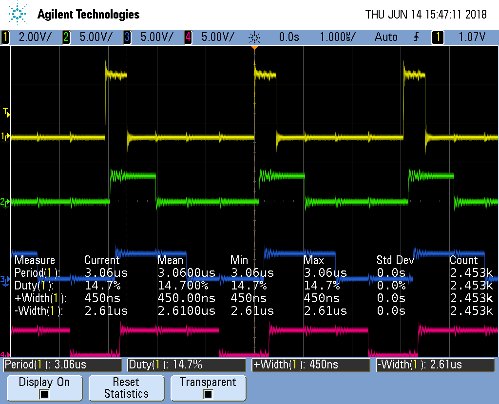
From the 'scope you see a 1 cycle on time results in a 450ns wide pulse and a 3.06us period is 326KHz, much slower than the 10ns pulse we saw before. But it may be more than fast enough for many applications. For example, most servos run at 50Hz.
But we can do better.
1.5. Loop Unrolling for Better Performance
Problem
The ARM controlled PRU code runs too slowly.
Solution
Simple loop unrolling can greatly improve the speed. pwm5.pru0.c is our unrolled
version.
  1
2
3
4
5
6
7
8
9
10
11
12
13
14
15
16
17
18
19
20
21
22
23
24
25
26
27
28
29
30
31
32
33
34
35
36
37
38
39
40
41
42
43
44
45
46
47
48
49
50
51
52
53

  // This code does MAXCH parallel PWM channels.
// It's period is 510ns.
#include <stdint.h>
#include <pru_cfg.h>
#include "resource_table_empty.h"

#define PRU0_DRAM       0x00000         // Offset to DRAM
// Skip the first 0x200 byte of DRAM since the Makefile allocates
// 0x100 for the STACK and 0x100 for the HEAP.
volatile unsigned int *pru0_dram = (unsigned int *) (PRU0_DRAM + 0x200);

#define MAXCH   4   // Maximum number of channels per PRU

#define update(ch) \
            if(onCount[ch]) {           \
                onCount[ch]--;          \
                __R30 |= 0x1<<ch;       \
            } else if(offCount[ch]) {   \
                offCount[ch]--;         \
                __R30 &= ~(0x1<<ch);    \
            } else {                    \
                onCount[ch] = pru0_dram[2*ch];  \
                offCount[ch]= pru0_dram[2*ch+1];    \
            }

volatile register uint32_t __R30;
volatile register uint32_t __R31;

void main(void)
{
    uint32_t ch;
    uint32_t on[]  = {1, 2, 3, 4};
    uint32_t off[] = {4, 3, 2, 1};
    uint32_t onCount[MAXCH], offCount[MAXCH];

    /* Clear SYSCFG[STANDBY_INIT] to enable OCP master port */
    CT_CFG.SYSCFG_bit.STANDBY_INIT = 0;

#pragma UNROLL(MAXCH)
    for(ch=0; ch<MAXCH; ch++) {
        pru0_dram[2*ch  ] = on[ch];     // Copy to DRAM0 so the ARM can change it
        pru0_dram[2*ch+1] = off[ch];    // Interleave the on and off values
        onCount[ch] = on[ch];
        offCount[ch]= off[ch];
    }

    while (1) {
        update(0)
        update(1)
        update(2)
        update(3)
    }
}
The output of pwm5.pru0.c is in the figure below.
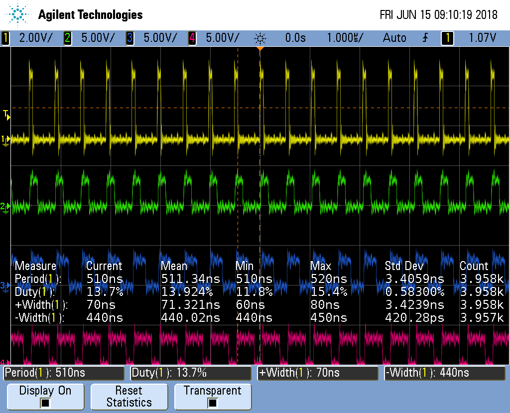
It’s running about 6 times faster than pwm4.pru0.c.
| Measure | pwm4.pru0.c time | pwm5.pru0.c time | Speedup | pwm5.pru0.c w/o UNROLL | Speedup |
|---|---|---|---|---|---|
Period |
3.06μs |
510ns |
6x |
1.81μs |
~1.7x |
Width+ |
450ns |
70ns |
~6x |
1.56μs |
~.3x |
Not a bad speed up for just a couple of simple changes.
Discussion
Here’s how it works.
First look at line 39. You see #pragma UNROLL(MAXCH) which is a pragma
that tells the compiler to unroll the loop that follows. We are unrolling it
MAXCH times (four times in this example). Just removing the pragma causes
the speedup compared to the pwm4.pru0.c case to drop from 6x to only 1.7x.
We also have our for loop inside the while loop that can be unrolled.
Unfortunately UNROLL() doesn’t work on it, therefore we have to do it by
hand. We could take the loop and just copy it three times, but that would
make it harder to maintain the code. Instead I convered the loop into a
#define (lines 14-24) and invoked update() as needed (lines 48-51).
This is not a function call. Whenever the preprocessor sees the update()
it copies the code an then it’s compiled.
This unrolling gets us an impressive 6x speedup.
1.6. Making All the Pulses Start at the Same Time
Problem
I have a mutlichannel PWM working, but the pulses aren’t synchronized, that is they don’t all start at the same time.
Solution
pwm5.pru0 Zoomed In is a zoomed in version of the previous figure. Notice the pulse in each channel starts about 15ns later than the channel above it.
The solution is to declare Rtmp (line 35) which holds the value for __R30.
  1
2
3
4
5
6
7
8
9
10
11
12
13
14
15
16
17
18
19
20
21
22
23
24
25
26
27
28
29
30
31
32
33
34
35
36
37
38
39
40
41
42
43
44
45
46
47
48
49
50
51
52
53
54
55
56

  // This code does MAXCH parallel PWM channels.
// All channels start at the same time. It's period is 510ns
#include <stdint.h>
#include <pru_cfg.h>
#include "resource_table_empty.h"

#define PRU0_DRAM       0x00000         // Offset to DRAM
// Skip the first 0x200 byte of DRAM since the Makefile allocates
// 0x100 for the STACK and 0x100 for the HEAP.
volatile unsigned int *pru0_dram = (unsigned int *) (PRU0_DRAM + 0x200);

#define MAXCH   4   // Maximum number of channels per PRU

#define update(ch) \
            if(onCount[ch]) {           \
                onCount[ch]--;          \
                Rtmp |= 0x1<<ch;        \
            } else if(offCount[ch]) {   \
                offCount[ch]--;         \
                Rtmp &= ~(0x1<<ch); \
            } else {                    \
                onCount[ch] = pru0_dram[2*ch];  \
                offCount[ch]= pru0_dram[2*ch+1];    \
            }

volatile register uint32_t __R30;
volatile register uint32_t __R31;

void main(void)
{
    uint32_t ch;
    uint32_t on[]  = {1, 2, 3, 4};
    uint32_t off[] = {4, 3, 2, 1};
    uint32_t onCount[MAXCH], offCount[MAXCH];
    register uint32_t Rtmp;

    /* Clear SYSCFG[STANDBY_INIT] to enable OCP master port */
    CT_CFG.SYSCFG_bit.STANDBY_INIT = 0;

#pragma UNROLL(MAXCH)
    for(ch=0; ch<MAXCH; ch++) {
        pru0_dram[2*ch  ] = on[ch];     // Copy to DRAM0 so the ARM can change it
        pru0_dram[2*ch+1] = off[ch];    // Interleave the on and off values
        onCount[ch] = on[ch];
        offCount[ch]= off[ch];
    }
    Rtmp = __R30;

    while (1) {
        update(0)
        update(1)
        update(2)
        update(3)
        __R30 = Rtmp;
    }
}
Each channel writes it’s value to Rtmp (lines 17 and 20) and then after
each channel has updated, Rtmp is copied to __R30 (line 54).
Discussion
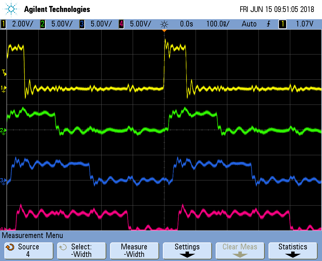
The following figure shows the channel are sync’ed. Though the period is slightly longer than before.
1.7. Adding More Channels via PRU 1
Problem
You need more output channels, or you need to shorten the period.
Solution
PRU 0 can output up to eight output pins (see Mapping bit positions to pin names). The code presented so far can be easily extended to use the eight output pins.
But what if you need more channels? You can always use PRU1, it has 14 output pins.
Or, what if four channels is enough, but you need a shorter period. Everytime you add a channel, the overall period gets longer. Twice as many channels means twice as long a period. If you move half the channels to PRU 1, you will make the period half as long.
Here’s the code (pwm7.pru0.c)
  1
2
3
4
5
6
7
8
9
10
11
12
13
14
15
16
17
18
19
20
21
22
23
24
25
26
27
28
29
30
31
32
33
34
35
36
37
38
39
40
41
42
43
44
45
46
47
48
49
50
51
52
53
54
55
56
57

  // This code does MAXCH parallel PWM channels on both PRU 0 and PRU 1
// All channels start at the same time. But the PRU 1 ch have a difference period
// It's period is 370ns
#include <stdint.h>
#include <pru_cfg.h>
#include "resource_table_empty.h"

#define PRUNUM 0

#define PRU0_DRAM       0x00000         // Offset to DRAM
// Skip the first 0x200 byte of DRAM since the Makefile allocates
// 0x100 for the STACK and 0x100 for the HEAP.
volatile unsigned int *pru0_dram = (unsigned int *) (PRU0_DRAM + 0x200);

#define MAXCH   2   // Maximum number of channels per PRU

#define update(ch) \
            if(onCount[ch]) {           \
                onCount[ch]--;          \
                Rtmp |= 0x1<<ch;        \
            } else if(offCount[ch]) {   \
                offCount[ch]--;         \
                Rtmp &= ~(0x1<<ch); \
            } else {                    \
                onCount[ch] = pru0_dram[2*ch];  \
                offCount[ch]= pru0_dram[2*ch+1];    \
            }

volatile register uint32_t __R30;
volatile register uint32_t __R31;

void main(void)
{
    uint32_t ch;
    uint32_t on[]  = {1, 2, 3, 4};
    uint32_t off[] = {4, 3, 2, 1};
    uint32_t onCount[MAXCH], offCount[MAXCH];
    register uint32_t Rtmp;

    /* Clear SYSCFG[STANDBY_INIT] to enable OCP master port */
    CT_CFG.SYSCFG_bit.STANDBY_INIT = 0;

#pragma UNROLL(MAXCH)
    for(ch=0; ch<MAXCH; ch++) {
        pru0_dram[2*ch  ] = on [ch+PRUNUM*MAXCH];   // Copy to DRAM0 so the ARM can change it
        pru0_dram[2*ch+1] = off[ch+PRUNUM*MAXCH];   // Interleave the on and off values
        onCount[ch] = on [ch+PRUNUM*MAXCH];
        offCount[ch]= off[ch+PRUNUM*MAXCH];
    }
    Rtmp = __R30;

    while (1) {
        update(0)
        update(1)
        __R30 = Rtmp;
    }
}
Be sure to run pwm7_setup.sh to get the correct pins configured.
#!/bin/bash
#
export TARGET=pwm7.pru0
echo TARGET=$TARGET

# Configure the PRU pins based on which Beagle is running
machine=$(awk '{print $NF}' /proc/device-tree/model)
echo -n $machine
if [ $machine = "Black" ]; then
    echo " Found"
    pins="P9_31 P9_29 P8_45 P8_46"
elif [ $machine = "Blue" ]; then
    echo " Found"
    pins=""
elif [ $machine = "PocketBeagle" ]; then
    echo " Found"
    pins="P1_36 P1_33"
else
    echo " Not Found"
    pins=""
fi

for pin in $pins
do
    echo $pin
    config-pin $pin pruout
    config-pin -q $pin
done
This makes sure the PRU 1 pins are properly configured.
Here we have a second pwm7 file. pwm7.pru1.c is identical to pwm7.pru0.c
except PRUNUM is set to 1, instead of 0.
Compile and run the two files with:
bone$ make TARGET=pwm7.pru0; make TARGET=pwm7.pru1
/var/lib/cloud9/common/Makefile:29: MODEL=TI_AM335x_BeagleBone_Black,TARGET=pwm7.pru0
-    Stopping PRU 0
-   copying firmware file /tmp/cloud9-examples/pwm7.pru0.out to /lib/firmware/am335x-pru0-fw
write_init_pins.sh
-    Starting PRU 0
MODEL   = TI_AM335x_BeagleBone_Black
PROC    = pru
PRUN    = 0
PRU_DIR = /sys/class/remoteproc/remoteproc1
/var/lib/cloud9/common/Makefile:29: MODEL=TI_AM335x_BeagleBone_Black,TARGET=pwm7.pru1
-    Stopping PRU 1
-   copying firmware file /tmp/cloud9-examples/pwm7.pru1.out to /lib/firmware/am335x-pru1-fw
write_init_pins.sh
-    Starting PRU 1
MODEL   = TI_AM335x_BeagleBone_Black
PROC    = pru
PRUN    = 1
PRU_DIR = /sys/class/remoteproc/remoteproc2
This will first stop, compile and start PRU 0, then do the same for PRU 1.
Moving half of the channels to PRU1 dropped the period from 510ns to 370ns, so we gained a bit.
Discussion
There weren’t many changes to be made. Line 15 we set MAXCH to 2. Lines 44-48 is where the big change is.
        pru0_dram[2*ch  ] = on [ch+PRUNUN*MAXCH];   // Copy to DRAM0 so the ARM can change it
        pru0_dram[2*ch+1] = off[ch+PRUNUN*MAXCH];   // Interleave the on and off values
        onCount[ch] = on [ch+PRUNUN*MAXCH];
        offCount[ch]= off[ch+PRUNUN*MAXCH];
If we are compiling for PRU 0, on[ch+PRUNUN*MAXCH] becomes on[ch+0*2] which is
on[ch] which is what we had before. But now if we are on PRU 1 it becomes
on[ch+1*2] which is on[ch+2]. That means we are picking up the second
half of the on and off arrays. The first half goes to PRU 0, the second to
PRU 1. So the same code can be used for both PRUs, but we get slightly different
behavior.
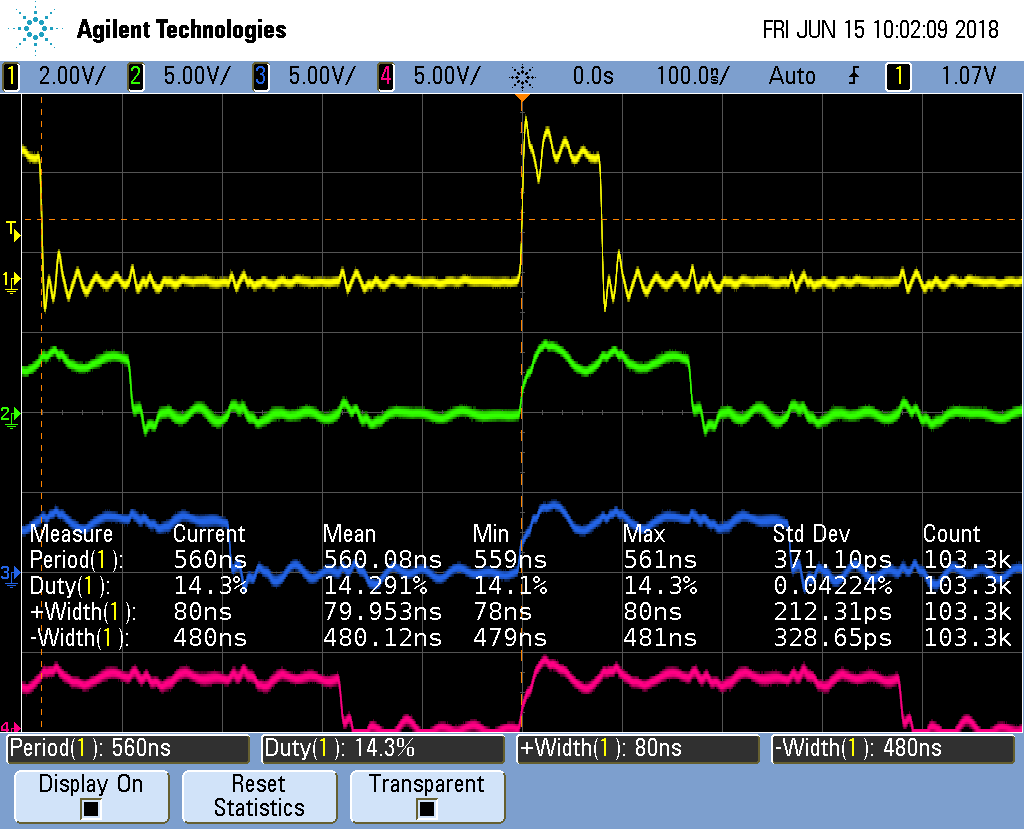
Running the code you will see the next figure.
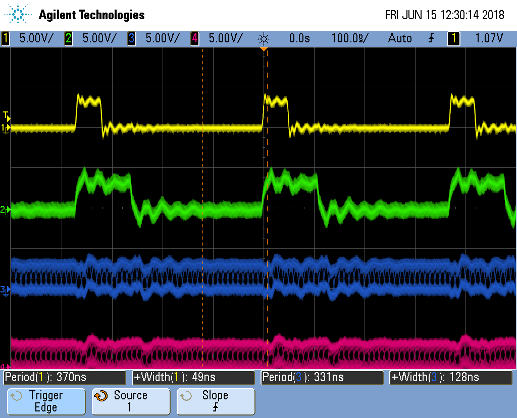
What’s going on there, the first channels look fine, but the PRU 1 channels are blurred. To see what’s happening, let’s stop the oscilloscope.
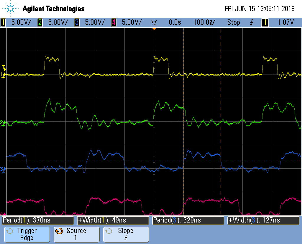
The stopped display shows that the four channels are doing what we wanted, except The PRU 0 channels have a period of 370ns while the PRU 1 channels at 330ns. It appears the compiler has optimied the two PRUs slightly differenty.
1.8. Synchronizing Two PRUs
Problem
I need to synchronize the two PRUs so they run together.
Solution
Use the Interrupt Controller (INTC). It allows one PRU to signal the other.
Page 225 of the
AM335x Technical Reference Manual
has details of how it works. Here’s the code for PRU 0, which at the end of the
while loop signals PRU 1 to start(pwm8.pru0.c).
  1
2
3
4
5
6
7
8
9
10
11
12
13
14
15
16
17
18
19
20
21
22
23
24
25
26
27
28
29
30
31
32
33
34
35
36
37
38
39
40
41
42
43
44
45
46
47
48
49
50
51
52
53
54
55
56
57
58
59
60
61
62
63
64
65
66
67
68
69
70
71
72
73
74
75
76
77
78

  // This code does MAXCH parallel PWM channels on both PRU 0 and PRU 1
// All channels start at the same time.
// It's period is 430ns
#include <stdint.h>
#include <pru_cfg.h>
#include <pru_intc.h>
#include <pru_ctrl.h>
#include "resource_table_empty.h"

#define PRUNUM 0

#define PRU0_DRAM       0x00000         // Offset to DRAM
// Skip the first 0x200 byte of DRAM since the Makefile allocates
// 0x100 for the STACK and 0x100 for the HEAP.
volatile unsigned int *pru0_dram = (unsigned int *) (PRU0_DRAM + 0x200);

#define MAXCH   2   // Maximum number of channels per PRU

#define update(ch) \
            if(onCount[ch]) {           \
                onCount[ch]--;          \
                Rtmp |= 0x1<<ch;        \
            } else if(offCount[ch]) {   \
                offCount[ch]--;         \
                Rtmp &= ~(0x1<<ch); \
            } else {                    \
                onCount[ch] = pru0_dram[2*ch];  \
                offCount[ch]= pru0_dram[2*ch+1];    \
            }

volatile register uint32_t __R30;
volatile register uint32_t __R31;

// Initialize interupts so the PRUs can be syncronized.
// PRU1 is started first and then waits for PRU0
// PRU0 is then started and tells PRU1 when to start going
void configIntc(void) {
    __R31 = 0x00000000;                 // Clear any pending PRU-generated events
    CT_INTC.CMR4_bit.CH_MAP_16 = 1;     // Map event 16 to channel 1
    CT_INTC.HMR0_bit.HINT_MAP_1 = 1;    // Map channel 1 to host 1
    CT_INTC.SICR = 16;                  // Ensure event 16 is cleared
    CT_INTC.EISR = 16;                  // Enable event 16
    CT_INTC.HIEISR |= (1 << 0);         // Enable Host interrupt 1
    CT_INTC.GER = 1;                    // Globally enable host interrupts
}

void main(void)
{
    uint32_t ch;
    uint32_t on[]  = {1, 2, 3, 4};
    uint32_t off[] = {4, 3, 2, 1};
    uint32_t onCount[MAXCH], offCount[MAXCH];
    register uint32_t Rtmp;

    CT_CFG.GPCFG0 = 0x0000;             // Configure GPI and GPO as Mode 0 (Direct Connect)
    configIntc();                       // Configure INTC

    /* Clear SYSCFG[STANDBY_INIT] to enable OCP master port */
    CT_CFG.SYSCFG_bit.STANDBY_INIT = 0;

#pragma UNROLL(MAXCH)
    for(ch=0; ch<MAXCH; ch++) {
        pru0_dram[2*ch  ] = on [ch+PRUNUM*MAXCH];   // Copy to DRAM0 so the ARM can change it
        pru0_dram[2*ch+1] = off[ch+PRUNUM*MAXCH];   // Interleave the on and off values
        onCount[ch] = on [ch+PRUNUM*MAXCH];
        offCount[ch]= off[ch+PRUNUM*MAXCH];
    }
    Rtmp = __R30;

    while (1) {
        __R30 = Rtmp;
        update(0)
        update(1)
#define PRU0_PRU1_EVT 16
        __R31 = (PRU0_PRU1_EVT-16) | (0x1<<5);  //Tell PRU 1 to start
        __delay_cycles(1);
    }
}
PRU 2’s code waits for PRU 0 before going.
  1
2
3
4
5
6
7
8
9
10
11
12
13
14
15
16
17
18
19
20
21
22
23
24
25
26
27
28
29
30
31
32
33
34
35
36
37
38
39
40
41
42
43
44
45
46
47
48
49
50
51
52
53
54
55
56
57
58
59
60
61
62
63
64
65
66

  // This code does MAXCH parallel PWM channels on both PRU 0 and PRU 1
// All channels start at the same time.
// It's period is 430ns
#include <stdint.h>
#include <pru_cfg.h>
#include <pru_intc.h>
#include <pru_ctrl.h>
#include "resource_table_empty.h"

#define PRUNUM 1

#define PRU0_DRAM       0x00000         // Offset to DRAM
// Skip the first 0x200 byte of DRAM since the Makefile allocates
// 0x100 for the STACK and 0x100 for the HEAP.
volatile unsigned int *pru0_dram = (unsigned int *) (PRU0_DRAM + 0x200);

#define MAXCH   2   // Maximum number of channels per PRU

#define update(ch) \
            if(onCount[ch]) {           \
                onCount[ch]--;          \
                Rtmp |= 0x1<<ch;        \
            } else if(offCount[ch]) {   \
                offCount[ch]--;         \
                Rtmp &= ~(0x1<<ch); \
            } else {                    \
                onCount[ch] = pru0_dram[2*ch];  \
                offCount[ch]= pru0_dram[2*ch+1];    \
            }

volatile register uint32_t __R30;
volatile register uint32_t __R31;

// Initialize interupts so the PRUs can be syncronized.
// PRU1 is started first and then waits for PRU0
// PRU0 is then started and tells PRU1 when to start going

void main(void)
{
    uint32_t ch;
    uint32_t on[]  = {1, 2, 3, 4};
    uint32_t off[] = {4, 3, 2, 1};
    uint32_t onCount[MAXCH], offCount[MAXCH];
    register uint32_t Rtmp;

    /* Clear SYSCFG[STANDBY_INIT] to enable OCP master port */
    CT_CFG.SYSCFG_bit.STANDBY_INIT = 0;

#pragma UNROLL(MAXCH)
    for(ch=0; ch<MAXCH; ch++) {
        pru0_dram[2*ch  ] = on [ch+PRUNUM*MAXCH];   // Copy to DRAM0 so the ARM can change it
        pru0_dram[2*ch+1] = off[ch+PRUNUM*MAXCH];   // Interleave the on and off values
        onCount[ch] = on [ch+PRUNUM*MAXCH];
        offCount[ch]= off[ch+PRUNUM*MAXCH];
    }
    Rtmp = __R30;

    while (1) {
        while((__R31 & (0x1<<31))==0) {     // Wait for PRU 0
        }
        CT_INTC.SICR = 16;                  // Clear event 16
        __R30 = Rtmp;
        update(0)
        update(1)
    }
}
In pwm8.pru0.c PRU 1 waits for a signal from PRU 0, so be sure to start PRU 1 first.
bone$ make TARGET=pwm8.pru0; make TARGET=pwm8.pru1Discussion
The figure below shows the two PRUs are synchronized, though there is some extra overhead in the process so the period is longer.
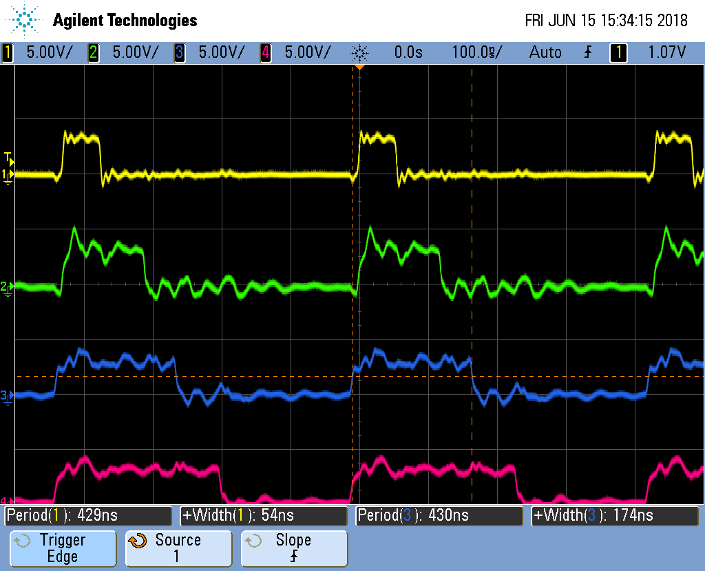
This isn’t much different from the previous examples.
| PRU | Line | Change |
|---|---|---|
0 |
37-45 |
For PRU 0 these define |
0 |
55-56 |
Set a configuration register and call |
1 |
59-61 |
PRU 1 then waits for PRU 0 to signal it. Bit 31 of |
0 |
74-75 |
On PRU 0 this generates the interupt to send to PRU 1. I found PRU 1 was slow to respond to the interupt, so I put this code at the end of the loop to give time for the signal to get to PRU 1. |
This ends the multipart pwm example.
1.9. Reading an Input at Regular Intervals
Problem
You have an input pin that needs to be read at regular intervals.
Solution
You can use the __R31 register to read an input pin. Let’s use the following
pins.
Direction |
Bit number |
Black |
AI (ICSS2) |
|
out |
0 |
P9_31 |
P8_44 |
P1.36 |
in |
7 |
P9_25 |
P8_36 |
P1.29 |
These values came from Mapping bit positions to pin names.
Configure the pins with input_setup.sh.
  1
2
3
4
5
6
7
8
9
10
11
12
13
14
15
16
17
18
19
20
21
22
23
24
25
26
27

  #!/bin/bash
#
export TARGET=input.pru0
echo TARGET=$TARGET

# Configure the PRU pins based on which Beagle is running
machine=$(awk '{print $NF}' /proc/device-tree/model)
echo -n $machine
if [ $machine = "Black" ]; then
    echo " Found"
    config-pin P9_31 pruout
    config-pin -q P9_31
    config-pin P9_25 pruin
    config-pin -q P9_25
elif [ $machine = "Blue" ]; then
    echo " Found"
    pins=""
elif [ $machine = "PocketBeagle" ]; then
    echo " Found"
    config-pin P1_36 pruout
    config-pin -q P1_36
    config-pin P1_29 pruin
    config-pin -q P1_29
else
    echo " Not Found"
    pins=""
fi
The following code reads the input pin and writes its value to the output pin.
  1
2
3
4
5
6
7
8
9
10
11
12
13
14
15
16
17
18
19
20
21
22
23
24
25

  #include <stdint.h>
#include <pru_cfg.h>
#include "resource_table_empty.h"

volatile register uint32_t __R30;
volatile register uint32_t __R31;

void main(void)
{
    uint32_t led;
    uint32_t sw;

    /* Clear SYSCFG[STANDBY_INIT] to enable OCP master port */
    CT_CFG.SYSCFG_bit.STANDBY_INIT = 0;

    led = 0x1<<0;   // P9_31 or P1_36
    sw  = 0x1<<7;   // P9_25 or P1_29

    while (1) {
        if((__R31&sw) == sw) {
            __R30 |= led;       // Turn on LED
        } else
            __R30 &= ~led;      // Turn off LED
    }
}
Discussion
Just remember that __R30 is for outputs and __R31 is
for inputs.
1.10. Analog Wave Generator
Problem
I want to generate an analog output, but only have GPIO pins.
Solution
The Beagle doesn’t have a built-in analog to digital converter. You could get a USB Audio Dongle which are under $10. But here we’ll take another approach.
Earlier we generated a PWM signal. Here we’ll generate a PWM whose duty cycle changes with time. A small duty cycle for when the output signal is small and a large duty cycle for when it is large.
This example was inspired by A PRU Sin Wave Generator in chapter 13 of Exploring BeagleBone by Derek Molloy.
Here’s the code.
  1
2
3
4
5
6
7
8
9
10
11
12
13
14
15
16
17
18
19
20
21
22
23
24
25
26
27
28
29
30
31
32
33
34
35
36
37
38
39
40
41
42
43
44
45
46
47
48
49
50
51
52
53
54
55
56
57
58

  // Generate an analog waveform and use a filter to reconstruct it.
#include <stdint.h>
#include <pru_cfg.h>
#include "resource_table_empty.h"
#include <math.h>

#define MAXT    100 // Maximum number of time samples
#define SAWTOOTH    // Pick which waveform

volatile register uint32_t R30;
volatile register uint32_t R31;

void main(void)
{
    uint32_t onCount;       // Current count for 1 out
    uint32_t offCount;      // count for 0 out
    uint32_t i;
    uint32_t waveform[MAXT]; // Waveform to be produced

    // Generate a periodic wave in an array of MAXT values
#ifdef SAWTOOTH
    for(i=0; i<MAXT; i++) {
        waveform[i] = i*100/MAXT;
    }
#endif
#ifdef TRIANGLE
    for(i=0; i<MAXT/2; i++) {
        waveform[i]        = 2i100/MAXT;
        waveform[MAXT-i-1] = 2i100/MAXT;
    }
#endif
#ifdef SINE
    float gain = 50.0f;
    float bias = 50.0f;
    float freq = 2.0f * 3.14159f / MAXT;
    for (i=0; i<MAXT; i++){
        waveform[i] = (uint32_t)(bias+gain*sin(i*freq));
    }
#endif

    /* Clear SYSCFG[STANDBY_INIT] to enable OCP master port */
    CT_CFG.SYSCFG_bit.STANDBY_INIT = 0;

    while (1) {
        // Generate a PWM signal whose duty cycle matches
        // the amplitude of the signal.
        for(i=0; i<MAXT; i++) {
            onCount = waveform[i];
            offCount = 100 - onCount;
            while(onCount--) {
                R30 |= 0x1<<4;        // Set the GPIO pin to 1
            }
            while(offCount--) {
                R30 &= ~(0x1<<4); // Clear the GPIO pin
            }
        }
    }
}
Set the #define at line 7 to the number of samples in one cycle of the waveform
and set the #define at line 8 to which waveform and then run make.
Discussion
The code has two parts. The first part (lines 21 to 39) generate the waveform
to be output. The #defines let you select which waveform you want to
generate. Since the output is a percent duty cycle, the values in waveform[]
must be between 0 and 100 inclusive. The waveform is only generated once, so
this part of the code isn’t time critical.
The second part (lines 44 to 54) uses the generated data to set the duty cycle of the PWM on a cycle-by-cycle basis. This part is time critical; the faster we can output the values, the higher the frequency of the output signal.
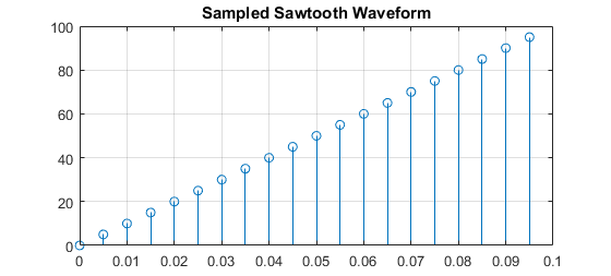
Suppose you want to generate a sawtooth waveform like the one shown in Continuous Sawtooth Waveform.
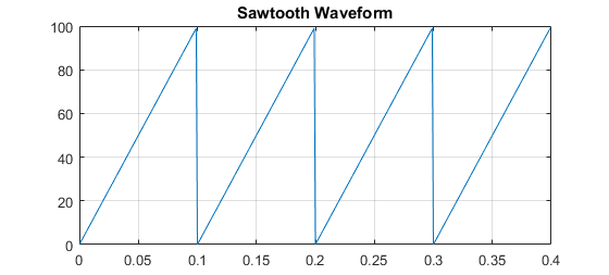
You need to sample the waveform and store one cycle. Sampled Sawtooth Waveform
shows a sampled version of the sawtooth. You need to generate MAXT samples;
here we show 20 samples, which may be enough. In the code MAXT is set to 100.
There’s a lot going on here; let’s take it line by line.
| Line | Explanation |
|---|---|
2-5 |
Standard c-header includes |
7 |
Number for samples in one cycle of the analog waveform |
8 |
Which waveform to use. We’ve defined SAWTOOTH, TRIANGLE and SINE, but you can define your own too. |
10-11 |
Declaring registers |
15-16 |
|
18 |
|
21-24 |
|
26-31 |
|
32-39 |
|
47 |
Here the |
48,49 |
|
50-52 |
Stay on for |
53-55 |
Now turn off for |
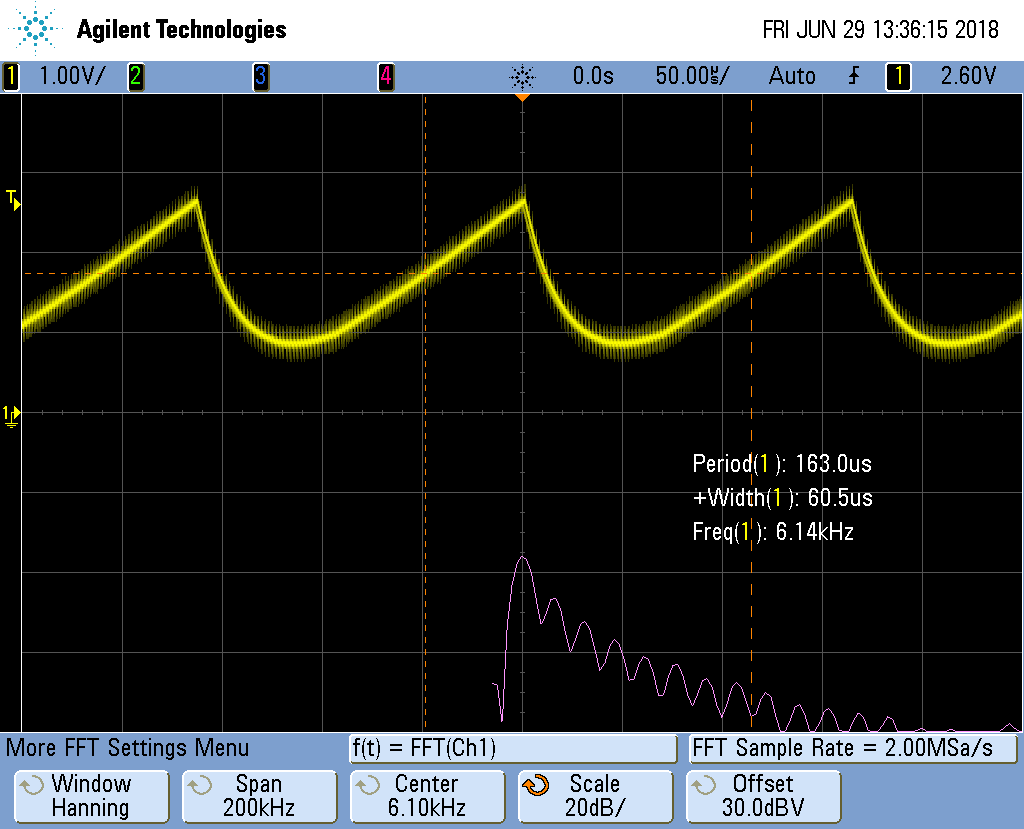
Unfiltered Sawtooth Waveform shows the output of the code.
It doesn’t look like a sawtooth; but if you look at the left side you will see each cycle has a longer and longer on time. The duty cycle is increasing. Once it’s almost 100% duty cycle, it switches to a very small duty cycle. Therefore it’s output what we programmed, but what we want is the average of the signal. The left hand side has a large (and increasing) average which would be for top of the sawtooth. The right hand side has a small average, which is what you want for the start of the sawtooth.
A simple low-pass filter, built with one resistor and one capacitor will do it. Low-Pass Filter Wiring Diagram shows how to wire it up.
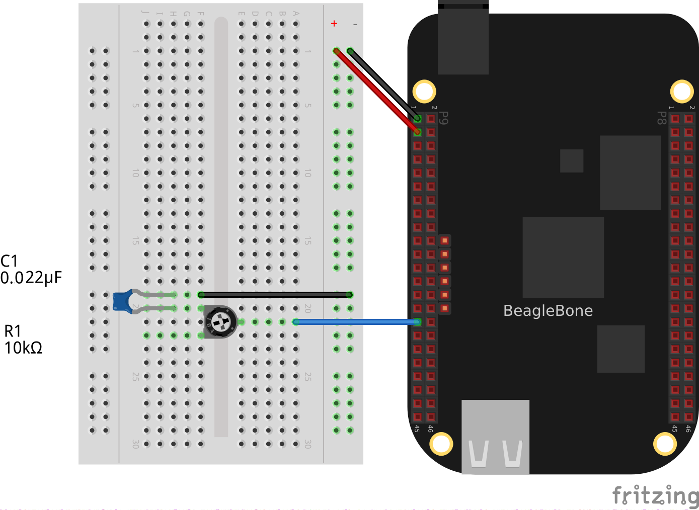
|
Note
|
I used a 10KΩ variable resistor and a 0.022μF capacitor. Probe the circuit between the resistor and the capacitor and adjust the resistor until you get a good looking waveform. |
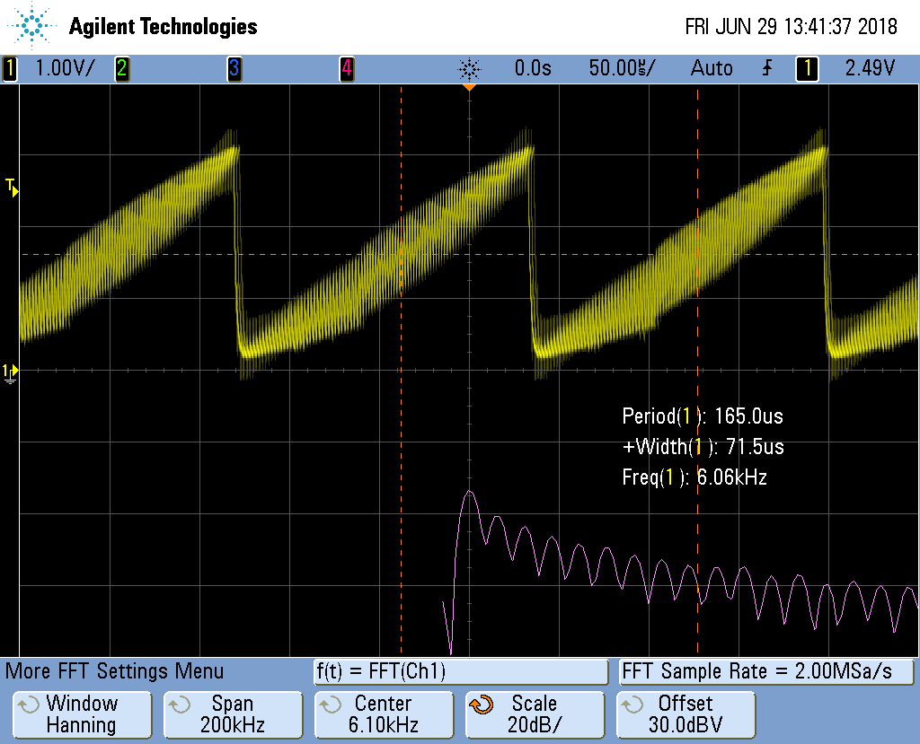
Reconstructed Sawtooth Waveform shows the results for filtered the SAWTOOTH.
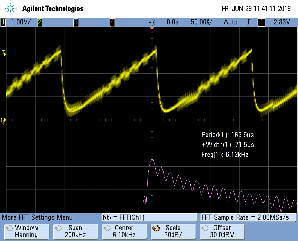
Now that looks more like a sawtooth wave. The top plot is the time-domain plot of the output of the low-pass filter. The bottom plot is the FFT of the top plot, therefore it’s the frequency domain. We are getting a sawtooth with a frequency of about 6.1KHz. You can see the fundamental frequency on the bottom plot along with several harmonics.
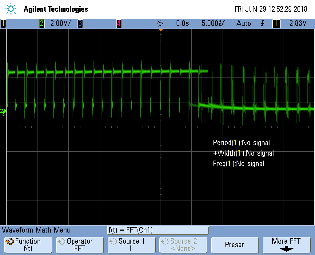
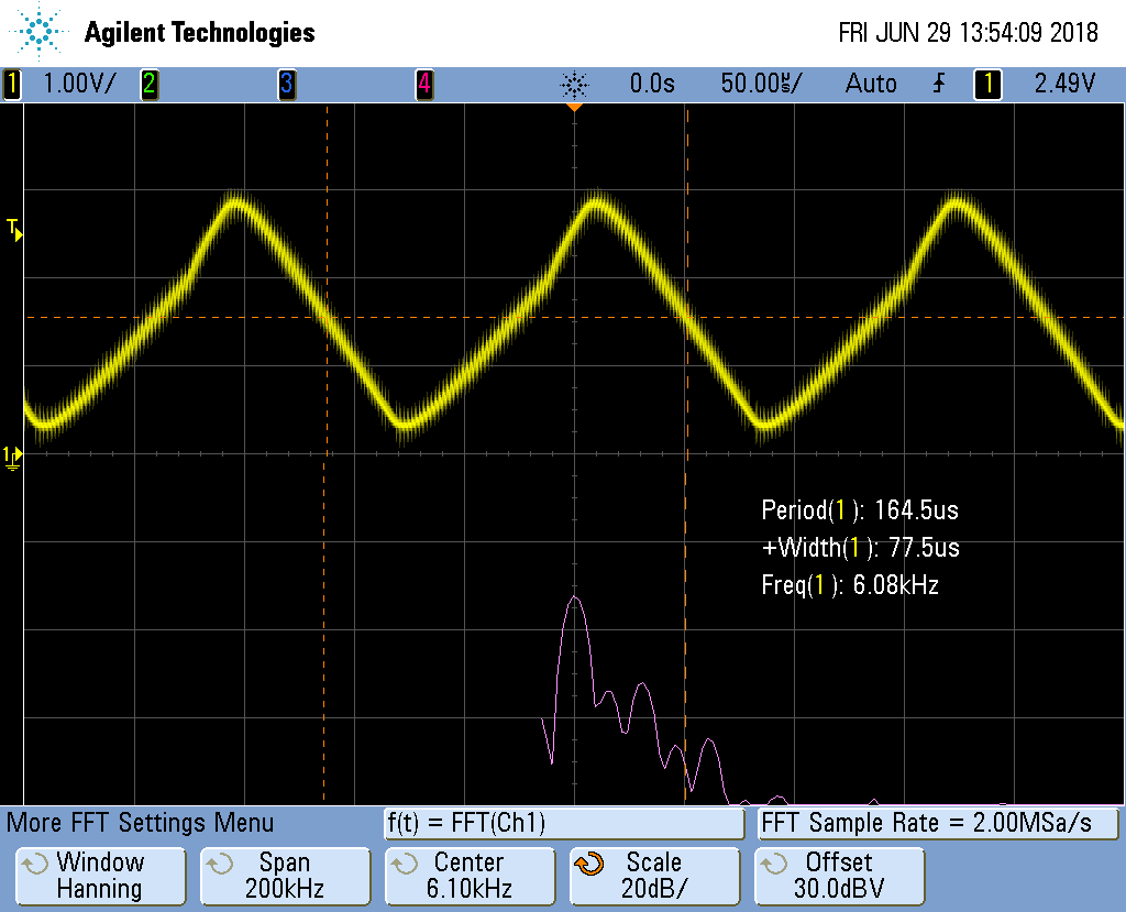
The top looks like a sawtooth wave, but there is a high freqnecy superimposed on it. We are only using a simple first-order filter. You could lower the cutoff freqnecy by adjusting the resistor. You’ll see something like Reconstructed Sawtooth Waveform with Lower Cutoff Frequency.
The high freqencies have been reduced, but the corner of the waveform has been rounded. You can also adjust the cutoff to a higher frequency and you’ll get a sharper corner, but you’ll also get more high frequencies. See Reconstructed Sawtooth Waveform with Higher Cutoff Frequency
Adjust to taste, though the real solution is to build a higher order filter. Search for second order filter and you’ll find some nice circuits.
You can adjust the frequency of the signal by adjusting MAXT. A smaller
MAXT will give a higher frequency. I’ve gotten good results with MAXT
as small as 20.
You can also get a triangle waveform by setting the #define.
Reconstructed Triangle Waveform shows the output signal.
And also the sine wave as shown in Reconstructed Sinusoid Waveform.
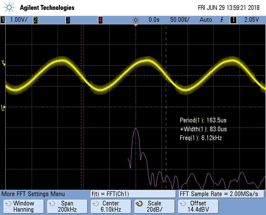
Notice on the bottom plot the harmonics are much more suppressed.
Generating the sine waveform uses floats. This requires much more code.
You can look in /tmp/cloud9-examples/sine.pru0.map to see how much memory is being used.
/tmp/cloud9-examples/sine.pru0.map for Sine Wave shows the first few lines for the sine wave.
  1
2
3
4
5
6
7
8
9
10
11
12
13
14
15
16
17
18
19
20
21
22

  ******************************************************************************
PRU Linker Unix v2.1.5
******************************************************************************
>> Linked Fri Jun 29 13:58:08 2018

OUTPUT FILE NAME:   </tmp/pru0-gen/sine1.out>
ENTRY POINT SYMBOL: "_c_int00_noinit_noargs_noexit"  address: 00000000


MEMORY CONFIGURATION

         name            origin    length      used     unused   attr    fill
----------------------  --------  ---------  --------  --------  ----  --------
PAGE 0:
  PRU_IMEM              00000000   00002000  000018c0  00000740  RWIX

PAGE 1:
  PRU_DMEM_0_1          00000000   00002000  00000154  00001eac  RWIX
  PRU_DMEM_1_0          00002000   00002000  00000000  00002000  RWIX

PAGE 2:
  PRU_SHAREDMEM         00010000   00003000  00000000  00003000  RWIX
Notice line 15 shows 0x18c0 bytes are being used for instructions. That’s 6336 in decimal.
Now compile for the sawtooth and you see only 444 byes are used. Floating-point requires over 5K more bytes. Use with care. If you are short on instruction space, you can move the table generation to the ARM and just copy the table to the PRU.
1.11. WS2812 (NeoPixel) driver
Problem
You have an Adafruit NeoPixel LED string or Adafruit NeoPixel LED matrix and want to light it up.
Solution
NeoPixel is Adafruit’s name for the WS2812 Intelligent control LED. Each NeoPixel contains a Red, Green and Blue LED with a PWM controller that can dim each one individually making a rainbow of colors possible. The NeoPixel is driven by a single serial line. The timing on the line is very sensesitive, which make the PRU a perfect candidate for driving it.
Wire the input to P9_29 and power to 3.3V and ground to ground as shown in
NeoPixel Wiring.
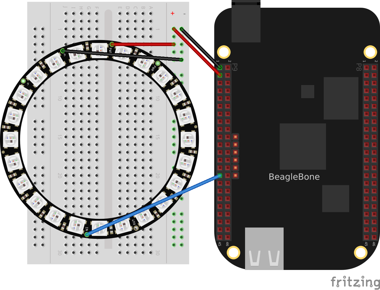
Test your wiring with the simple code in neo1.pru0.c - Code to turn all NeoPixels’s white which to turns all pixels white.
  1
2
3
4
5
6
7
8
9
10
11
12
13
14
15
16
17
18
19
20
21
22
23
24
25
26
27
28
29
30
31
32
33
34
35
36
37
38
39
40
41
42
43
44

  // Control a ws2812 (NeoPixel) display, All on or all off
#include <stdint.h>
#include <pru_cfg.h>
#include "resource_table_empty.h"
#include "prugpio.h"

#define STR_LEN 24
#define oneCyclesOn     700/5   // Stay on 700ns
#define oneCyclesOff    800/5
#define zeroCyclesOn    350/5
#define zeroCyclesOff   600/5
#define resetCycles     60000/5 // Must be at least 50u, use 60u
#define gpio P1_31              // output pin

#define ONE

volatile register uint32_t R30;
volatile register uint32_t R31;

void main(void)
{
    /* Clear SYSCFG[STANDBY_INIT] to enable OCP master port /
    CT_CFG.SYSCFG_bit.STANDBY_INIT = 0;

    uint32_t i;
    for(i=0; i<STR_LEN3*8; i++) {
#ifdef ONE
        R30 |= gpio;      // Set the GPIO pin to 1
        delay_cycles(oneCyclesOn-1);
        R30 &= ~gpio;     // Clear the GPIO pin
        delay_cycles(oneCyclesOff-2);
#else
        R30 |= gpio;      // Set the GPIO pin to 1
        delay_cycles(zeroCyclesOn-1);
        R30 &= ~gpio;     // Clear the GPIO pin
        delay_cycles(zeroCyclesOff-2);
#endif
    }
    // Send Reset
    R30 &= ~gpio; // Clear the GPIO pin
    delay_cycles(resetCycles);

    __halt();
}
Discussion
NeoPixel bit sequence (taken from WS2812 Data Sheet) shows the following waveforms are used to send a bit of data.
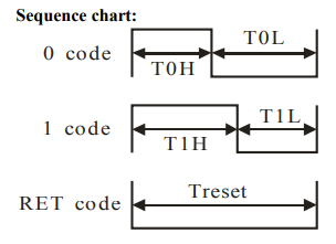
Where the times are:
| Label | Time in ns |
|---|---|
T0H |
350 |
T0L |
800 |
T1H |
700 |
T1L |
600 |
Treset |
>50,000 |
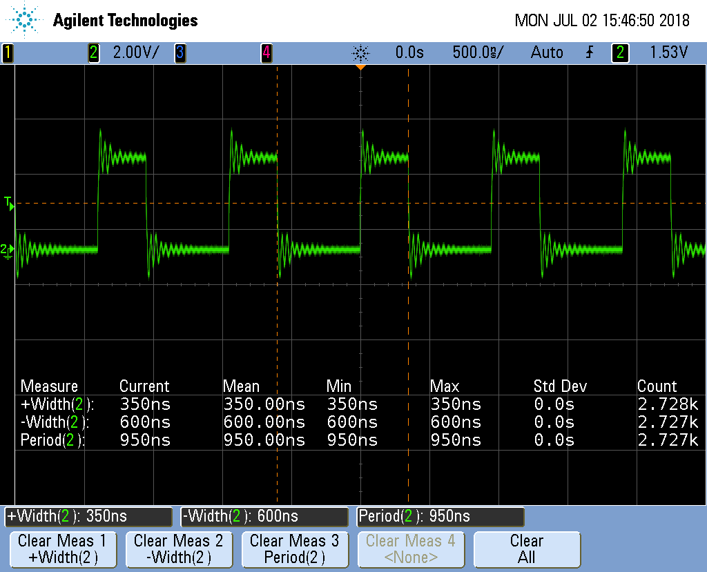
The code in neo1.pru0.c - Code to turn all NeoPixels’s white define these times in lines 7-10.
The /5 is because
each instruction take 5ns. Lines 27-30 then set the output to 1 for
the desired time and then to 0 and keeps repeating it for the entire
string length. NeoPixel zero timing
shows the waveform for sending a 0 value. Note the times are spot on.
Each NeoPixel listens for a RGB value. Once a value has arrived all other values that follow are passed on to the next NeoPixel which does the same thing. That way you can individually control all of the NeoPixels.
Lines 38-40 send out a reset pulse. If a NeoPixel sees a reset pulse it will grab the next value for itself and start over again.
1.12. Setting NeoPixels to Different Colors
Problem
I want to set the LEDs to different colors.
Solution
Wire your NeoPixels as shown in NeoPixel Wiring then run the code in neo2.pru0.c - Code to turn on green, red, blue.
  1
2
3
4
5
6
7
8
9
10
11
12
13
14
15
16
17
18
19
20
21
22
23
24
25
26
27
28
29
30
31
32
33
34
35
36
37
38
39
40
41
42
43
44
45
46

  // Control a ws2812 (neo pixel) display, green, red, blue, green, ...
#include <stdint.h>
#include <pru_cfg.h>
#include "resource_table_empty.h"
#include "prugpio.h"

#define STR_LEN 4
#define oneCyclesOn     700/5   // Stay on 700ns
#define oneCyclesOff    800/5
#define zeroCyclesOn    350/5
#define zeroCyclesOff   600/5
#define resetCycles     60000/5 // Must be at least 50u, use 60u
#define gpio P1_31              // output pin

volatile register uint32_t R30;
volatile register uint32_t R31;

void main(void)
{
    /* Clear SYSCFG[STANDBY_INIT] to enable OCP master port */
    CT_CFG.SYSCFG_bit.STANDBY_INIT = 0;

    uint32_t color[STR_LEN] = {0x0f0000, 0x000f00, 0x0000f, 0x0f0f0f};  // green, red, blue
    int i, j;

    for(j=0; j<STR_LEN; j++) {
        for(i=23; i>=0; i--) {
            if(color[j] & (0x1<<i)) {
                R30 |= gpio;      // Set the GPIO pin to 1
                delay_cycles(oneCyclesOn-1);
                R30 &= ~gpio;     // Clear the GPIO pin
                delay_cycles(oneCyclesOff-2);
            } else {
                R30 |= gpio;      // Set the GPIO pin to 1
                delay_cycles(zeroCyclesOn-1);
                R30 &= ~gpio;     // Clear the GPIO pin
                delay_cycles(zeroCyclesOff-2);
            }
        }
    }
    // Send Reset
    R30 &= ~gpio; // Clear the GPIO pin
    delay_cycles(resetCycles);

    __halt();
}
This will make the first LED green, the second red and the third blue.
Discussion
NeoPixel data sequence shows the sequence of bits used to control the green, red and blue values.

|
Note
|
The usual order for colors is RGB (red, green, blue), but the NeoPixels use GRB (green, red, blue). |
Line-by-line for neo2.pru0.c is the line-by-line for neo2.pru0.c.
| Line | Explanation |
|---|---|
23 |
Define the string of colors to be output. Here the ordering of the bits is the same as NeoPixel data sequence, GRB. |
26 |
Loop for each color to output. |
27 |
Loop for each bit in an GRB color. |
28 |
Get the jth color and mask off all but the ith bit. |
29-32 |
Send a 1. |
34-37 |
Send a 0. |
42-43 |
Send a reset pulse once all the colors have been sent. |
|
Note
|
This will only change the first |
1.13. Controlling Arbitrary LEDs
Problem
I want to change the 10th LED and not have to change the others.
Solution
You need to keep an array of colors for the whole string in the PRU. Change the color of any pixels you want in the array and then send out the whole string to the LEDs. neo3.pru0.c - Code to animate a red pixel running around a ring of blue shows an example animates a red pixel running around a ring of blue background. neo3.pru0.c - Simple animation shows the code in action.
  1
2
3
4
5
6
7
8
9
10
11
12
13
14
15
16
17
18
19
20
21
22
23
24
25
26
27
28
29
30
31
32
33
34
35
36
37
38
39
40
41
42
43
44
45
46
47
48
49
50
51
52
53
54
55
56
57
58
59
60
61
62
63
64
65
66
67

  // Control a ws2812 (neo pixel) display, green, red, blue, green, ...
#include <stdint.h>
#include <pru_cfg.h>
#include "resource_table_empty.h"
#include "prugpio.h"

#define STR_LEN 24
#define oneCyclesOn     700/5   // Stay on 700ns
#define oneCyclesOff    800/5
#define zeroCyclesOn    350/5
#define zeroCyclesOff   600/5
#define resetCycles     60000/5 // Must be at least 50u, use 60u
#define gpio P1_31              // output pin

#define SPEED 20000000/5        // Time to wait between updates

volatile register uint32_t R30;
volatile register uint32_t R31;

void main(void)
{
    uint32_t background = 0x00000f;
    uint32_t foreground = 0x000f00;

    /* Clear SYSCFG[STANDBY_INIT] to enable OCP master port */
    CT_CFG.SYSCFG_bit.STANDBY_INIT = 0;

    uint32_t color[STR_LEN];    // green, red, blue
    int i, j;
    int k, oldk = 0;;
    // Set everything to background
    for(i=0; i<STR_LEN; i++) {
        color[i] = background;
    }

    while(1) {
        // Move forward one position
        for(k=0; k<STR_LEN; k++) {
            color[oldk] = background;
            color[k]    = foreground;
            oldk=k;

            // Output the string
            for(j=0; j<STR_LEN; j++) {
                for(i=23; i>=0; i--) {
                    if(color[j] & (0x1<<i)) {
                        R30 |= gpio;      // Set the GPIO pin to 1
                        delay_cycles(oneCyclesOn-1);
                        R30 &= ~gpio;     // Clear the GPIO pin
                        delay_cycles(oneCyclesOff-2);
                    } else {
                        R30 |= gpio;      // Set the GPIO pin to 1
                        delay_cycles(zeroCyclesOn-1);
                        R30 &= ~gpio;     // Clear the GPIO pin
                        delay_cycles(zeroCyclesOff-2);
                    }
                }
            }
            // Send Reset
            R30 &= ~gpio; // Clear the GPIO pin
            delay_cycles(resetCycles);

            // Wait
            __delay_cycles(SPEED);
        }
    }
}
Discussion
Here’s the highlights.
| Line | Explanation |
|---|---|
32,33 |
Initiallize the array of colors. |
38-41 |
Update the array. |
44-58 |
Send the array to the LEDs. |
60-61 |
Send a reset. |
64 |
Wait a bit. |
1.14. Controlling NeoPixels Through a Kernel Driver
Problem
You want to control your NeoPixels through a kernel driver so you can control it
through a /dev interface.
Solution
The rpmsg_pru driver provides a way to pass data between the ARM processor and the PRUs. It’s already included on current images. neo4.pru0.c - Code to talk to the PRU via rpmsg_pru shows an example.
  1
2
3
4
5
6
7
8
9
10
11
12
13
14
15
16
17
18
19
20
21
22
23
24
25
26
27
28
29
30
31
32
33
34
35
36
37
38
39
40
41
42
43
44
45
46
47
48
49
50
51
52
53
54
55
56
57
58
59
60
61
62
63
64
65
66
67
68
69
70
71
72
73
74
75
76
77
78
79
80
81
82
83
84
85
86
87
88
89
90
91
92
93
94
95
96
97
98
99
100
101
102
103
104
105
106
107
108
109
110
111
112
113
114
115
116
117
118
119
120
121
122
123
124
125
126
127
128
129
130
131
132
133
134
135
136
137
138
139
140
141
142
143
144
145

  // Use rpmsg to control the NeoPixels via /dev/rpmsg_pru30
#include <stdint.h>
#include <stdio.h>
#include <stdlib.h>         // atoi
#include <string.h>
#include <pru_cfg.h>
#include <pru_intc.h>
#include <rsc_types.h>
#include <pru_rpmsg.h>
#include "resource_table_0.h"
#include "prugpio.h"

volatile register uint32_t R30;
volatile register uint32_t R31;

/* Host-0 Interrupt sets bit 30 in register R31 /
#define HOST_INT            ((uint32_t) 1 << 30)

/ The PRU-ICSS system events used for RPMsg are defined in the Linux device tree
 * PRU0 uses system event 16 (To ARM) and 17 (From ARM)
 * PRU1 uses system event 18 (To ARM) and 19 (From ARM)
 /
#define TO_ARM_HOST         16
#define FROM_ARM_HOST       17

/
* Using the name 'rpmsg-pru' will probe the rpmsg_pru driver found
* at linux-x.y.z/drivers/rpmsg/rpmsg_pru.c
/
#define CHAN_NAME           "rpmsg-pru"
#define CHAN_DESC           "Channel 30"
#define CHAN_PORT           30

/
 * Used to make sure the Linux drivers are ready for RPMsg communication
 * Found at linux-x.y.z/include/uapi/linux/virtio_config.h
 /
#define VIRTIO_CONFIG_S_DRIVER_OK   4

char payload[RPMSG_BUF_SIZE];

#define STR_LEN 24
#define oneCyclesOn     700/5   // Stay on for 700ns
#define oneCyclesOff    600/5
#define zeroCyclesOn    350/5
#define zeroCyclesOff   800/5
#define resetCycles     51000/5 // Must be at least 50u, use 51u
#define out P1_31               // Bit number to output on

#define SPEED 20000000/5        // Time to wait between updates

uint32_t color[STR_LEN];    // green, red, blue

/
 * main.c
 /
void main(void)
{
    struct pru_rpmsg_transport transport;
    uint16_t src, dst, len;
    volatile uint8_t *status;

    uint8_t r, g, b;
    int i, j;
    // Set everything to background
    for(i=0; i<STR_LEN; i++) {
        color[i] = 0x010000;
    }

    / Allow OCP master port access by the PRU so the PRU can read external memories /
    CT_CFG.SYSCFG_bit.STANDBY_INIT = 0;

    / Clear the status of the PRU-ICSS system event that the ARM will use to 'kick' us /
#ifdef CHIP_IS_am57xx
    CT_INTC.SICR_bit.STATUS_CLR_INDEX = FROM_ARM_HOST;
#else
    CT_INTC.SICR_bit.STS_CLR_IDX = FROM_ARM_HOST;
#endif

    / Make sure the Linux drivers are ready for RPMsg communication /
    status = &resourceTable.rpmsg_vdev.status;
    while (!(*status & VIRTIO_CONFIG_S_DRIVER_OK));

    / Initialize the RPMsg transport structure /
    pru_rpmsg_init(&transport, &resourceTable.rpmsg_vring0, &resourceTable.rpmsg_vring1, TO_ARM_HOST, FROM_ARM_HOST);

    / Create the RPMsg channel between the PRU and ARM user space using the transport structure. /
    while (pru_rpmsg_channel(RPMSG_NS_CREATE, &transport, CHAN_NAME, CHAN_DESC, CHAN_PORT) != PRU_RPMSG_SUCCESS);
    while (1) {
        / Check bit 30 of register R31 to see if the ARM has kicked us /
        if (R31 & HOST_INT) {
            / Clear the event status /
#ifdef CHIP_IS_am57xx
            CT_INTC.SICR_bit.STATUS_CLR_INDEX = FROM_ARM_HOST;
#else
            CT_INTC.SICR_bit.STS_CLR_IDX = FROM_ARM_HOST;
#endif
            / Receive all available messages, multiple messages can be sent per kick */
            while (pru_rpmsg_receive(&transport, &src, &dst, payload, &len) == PRU_RPMSG_SUCCESS) {
                char *ret;  // rest of payload after front character is removed
                int index;  // index of LED to control
                // Input format is:  index red green blue
                index = atoi(payload);
                // Update the array, but don't write it out.
                if((index >=0) & (index < STR_LEN)) {
                    ret = strchr(payload, ' '); // Skip over index
                    r = strtol(&ret[1], NULL, 0);
                    ret = strchr(&ret[1], ' '); // Skip over r, etc.
                    g = strtol(&ret[1], NULL, 0);
                    ret = strchr(&ret[1], ' ');
                    b = strtol(&ret[1], NULL, 0);

                    color[index] = (g<<16)|(r<<8)|b;    // String wants GRB
                }
                // When index is -1, send the array to the LED string
                if(index == -1) {
                    // Output the string
                    for(j=0; j<STR_LEN; j++) {
                        // Cycle through each bit
                        for(i=23; i>=0; i--) {
                            if(color[j] & (0x1<<i)) {
                                R30 |= out;       // Set the GPIO pin to 1
                                delay_cycles(oneCyclesOn-1);
                                R30 &= ~out;  // Clear the GPIO pin
                                delay_cycles(oneCyclesOff-14);
                            } else {
                                R30 |= out;       // Set the GPIO pin to 1
                                delay_cycles(zeroCyclesOn-1);
                                R30 &= ~(out);    // Clear the GPIO pin
                                delay_cycles(zeroCyclesOff-14);
                            }
                        }
                    }
                    // Send Reset
                    R30 &= ~out;  // Clear the GPIO pin
                    delay_cycles(resetCycles);

                    // Wait
                    delay_cycles(SPEED);
                }

            }
        }
    }
}
Run the code as usual.
bone$ make TARGET=neo4.pru0
/var/lib/cloud9/common/Makefile:29: MODEL=TI_AM335x_BeagleBone_Black,TARGET=neo4.pru0
-    Stopping PRU 0
-   copying firmware file /tmp/cloud9-examples/neo4.pru0.out to /lib/firmware/am335x-pru0-fw
write_init_pins.sh
-    Starting PRU 0
MODEL   = TI_AM335x_BeagleBone_Black
PROC    = pru
PRUN    = 0
PRU_DIR = /sys/class/remoteproc/remoteproc1

bone$ echo 0 0xff 0 127 > /dev/rpmsg_pru30
bone$ echo -1 > /dev/rpmsg_pru30
/dev/rpmsg_pru30 is a device driver that lets the ARM talk to the PRU.
The first echo says to set the 0th LED to RGB value 0xff 0 127. (Note: you can
mix hex and decimal.) The second echo tells the driver to send the data to the
LEDs. Your 0th LED should now be lit.
Discussion
There’s a lot here. I’ll just hit some of the highlights in Line-by-line for neo4.pru0.c.
| Line | Explanation |
|---|---|
30 |
The |
32 |
The |
40 |
|
42-48 |
Same as the previous NeoPixel examples. |
52 |
|
66-68 |
|
70-85 |
Here are a number of details needed to set up the channel between the PRU and the ARM. |
88 |
Here we wait until the ARM sends us some numbers. |
99 |
Receive all the data from the ARM, store it in |
101-111 |
The data sent is: index red green blue. Pull off the index. If it’s in the right range, pull off the red, green and blue values. |
113 |
The NeoPixels want the data in GRB order. Shift and OR everything together. |
116-133 |
If the |
You can now use programs running on the ARM to send colors to the PRU. neo-rainbow.py - A python program using /dev/rpmsg_pru30 shows an example.
  1
2
3
4
5
6
7
8
9
10
11
12
13
14
15
16
17
18
19
20
21
22
23
24
25
26
27

  !/usr/bin/python3
from time import sleep
import math

len = 24
amp = 12
f = 25
shift = 3
phase = 0

 Open a file
fo = open("/dev/rpmsg_pru30", "wb", 0)

while True:
    for i in range(0, len):
        r = (amp * (math.sin(2math.pi*f(i-phase-0shift)/len) + 1)) + 1;
        g = (amp * (math.sin(2*math.pi*f(i-phase-1shift)/len) + 1)) + 1;
        b = (amp * (math.sin(2*math.pi*f(i-phase-2*shift)/len) + 1)) + 1;
        fo.write(b"%d %d %d %d\n" % (i, r, g, b))
        # print("0 0 127 %d" % (i))

    fo.write(b"-1 0 0 0\n");
    phase = phase + 1
    sleep(0.05)

# Close opened file
fo.close()
Line 19 writes the data to the PRU. Be sure to have a newline, or space after the last number, or you numbers will get blurred together.
Switching from pru0 to pru1 with rpmsg_pru
There are three things you need to change when switching from pru0 to pru1 when using rpmsg_pru.
-
The include on line 10 is switched to
#include "resource_table_1.h"(0 is switched to a 1) -
Line 17 is switched to
#define HOST_INT ((uint32_t) 1 << 31)(30 is switched to 31.) -
Lines 23 and 24 are switched to:
#define TO_ARM_HOST         18
#define FROM_ARM_HOST       19
These changes switch to the proper channel numbers to use pru1 instead of pru0.
1.15. RGB LED Matrix - No Integrated Drivers
Problem
You have a RGB LED matrix (1.4. RGB LED Matrix - No Integrated Drivers) and want to know at a low level how the PRU works.
Solution
Here is the datasheet, but the best description I’ve found for the RGB Matrix is from Adafruit. I’ve reproduced it here, with adjustments for the 64x32 matrix we are using.
There’s zero documention out there on how these matrices work, and no public datasheets or spec sheets so we are going to try to document how they work.

First thing to notice is that there are 2048 RGB LEDs in a 64x32 matrix. Like pretty much every matrix out there, you can’t drive all 2048 at once. One reason is that would require a lot of current, another reason is that it would be really expensive to have so many pins. Instead, the matrix is divided into 16 interleaved sections/strips. The first section is the 1st 'line' and the 17th 'line' (64 x 2 RGB LEDs = 128 RGB LEDs), the second is the 2nd and 18th line, etc until the last section which is the 16th and 32nd line. You might be asking, why are the lines paired this way? wouldn’t it be nicer to have the first section be the 1st and 2nd line, then 3rd and 4th, until the 15th and 16th? The reason they do it this way is so that the lines are interleaved and look better when refreshed, otherwise we’d see the stripes more clearly.

So, on the PCB is 24 LED driver chips. These are like 74HC595s but they have 16 outputs and they are constant current. 16 outputs * 24 chips = 384 LEDs that can be controlled at once, and 128 * 3 (R G and B) = 384. So now the design comes together: You have 384 outputs that can control one line at a time, with each of 384 R, G and B LEDs either on or off. The controller (say an FPGA or microcontroller) selects which section to currently draw (using LA, LB, LC and LD address pins - 4 bits can have 16 values). Once the address is set, the controller clocks out 384 bits of data (48 bytes) and latches it. Then it increments the address and clocks out another 384 bits, etc until it gets to address #15, then it sets the address back to #0
That gives a good overview, but there are a few details missing. rgb_python.py - Python code for driving RGB LED matrix is a functioning python program that gives a nice high-level view of how to drive the display.
  1
2
3
4
5
6
7
8
9
10
11
12
13
14
15
16
17
18
19
20
21
22
23
24
25
26
27
28
29
30
31
32
33
34
35
36
37
38
39
40
41
42
43
44
45
46
47
48
49
50
51
52
53
54
55
56
57
58
59
60
61
62
63
64
65
66
67
68
69
70
71
72
73
74
75
76
77
78

  !/usr/bin/env python3
import Adafruit_BBIO.GPIO as GPIO

 Define which functions are connect to which pins
OE="P1_29"      # Output Enable, active low
LAT="P1_36"     # Latch, toggle after clocking in a row of pixels
CLK="P1_33"     # Clock, toggle after each pixel

# Input data pins
R1="P2_10"  # R1, G1, B1 are for the top rows (1-16) of pixels
G1="P2_8"
B1="P2_6"

R2="P2_4"   # R2, G2, B2 are for the bottom rows (17-32) of pixels
G2="P2_2"
B2="P2_1"

LA="P2_32"  # Address lines for which row (1-16 or 17-32) to update
LB="P2_30"
LC="P1_31"
LD="P2_34"

# Set everything as output ports
GPIO.setup(OE,  GPIO.OUT)
GPIO.setup(LAT, GPIO.OUT)
GPIO.setup(CLK, GPIO.OUT)

GPIO.setup(R1, GPIO.OUT)
GPIO.setup(G1, GPIO.OUT)
GPIO.setup(B1, GPIO.OUT)
GPIO.setup(R2, GPIO.OUT)
GPIO.setup(G2, GPIO.OUT)
GPIO.setup(B2, GPIO.OUT)

GPIO.setup(LA, GPIO.OUT)
GPIO.setup(LB, GPIO.OUT)
GPIO.setup(LC, GPIO.OUT)
GPIO.setup(LD, GPIO.OUT)

GPIO.output(OE,  0)     # Enable the display
GPIO.output(LAT, 0)     # Set latch to low

while True:
    for bank in range(64):
        GPIO.output(LA, bank>>0&0x1)    # Select rows
        GPIO.output(LB, bank>>1&0x1)
        GPIO.output(LC, bank>>2&0x1)
        GPIO.output(LD, bank>>3&0x1)

        # Shift the colors out.  Here we only have four different
        # colors to keep things simple.
        for i in range(16):
            GPIO.output(R1,  1)     # Top row, white
            GPIO.output(G1,  1)
            GPIO.output(B1,  1)

            GPIO.output(R2,  1)     # Bottom row, red
            GPIO.output(G2,  0)
            GPIO.output(B2,  0)

            GPIO.output(CLK, 0)     # Toggle clock
            GPIO.output(CLK, 1)

            GPIO.output(R1,  0)     # Top row, black
            GPIO.output(G1,  0)
            GPIO.output(B1,  0)

            GPIO.output(R2,  0)     # Bottom row, green
            GPIO.output(G2,  1)
            GPIO.output(B2,  0)

            GPIO.output(CLK, 0)     # Toggle clock
            GPIO.output(CLK, 1)

        GPIO.output(OE,  1)     # Disable display while updating
        GPIO.output(LAT, 1)     # Toggle latch
        GPIO.output(LAT, 0)
        GPIO.output(OE,  0)     # Enable display
Be sure to run the rgb_python_setup.sh script before running the python code.
  1
2
3
4
5
6
7
8
9
10
11
12
13
14
15
16
17
18
19
20
21
22
23
24
25
26
27
28
29
30
31
32
33
34
35
36
37
38
39
40
41

  !/bin/bash
 Setup for 64x32 RGB Matrix
export TARGET=rgb1.pru0
echo TARGET=$TARGET

# Configure the PRU pins based on which Beagle is running
machine=$(awk '{print $NF}' /proc/device-tree/model)
echo -n $machine
if [ $machine = "Black" ]; then
    echo " Found"
    pins=""
elif [ $machine = "Blue" ]; then
    echo " Found"
    pins=""
elif [ $machine = "PocketBeagle" ]; then
    echo " Found"
    prupins="P2_32 P1_31 P1_33 P1_29 P2_30 P2_34 P1_36"
    gpiopins="P2_10 P2_06 P2_04 P2_01 P2_08 P2_02"
    # Uncomment for J2
    # gpiopins="$gpiopins P2_27 P2_25 P2_05 P2_24 P2_22 P2_18"
else
    echo " Not Found"
    pins=""
fi

for pin in $prupins
do
    echo $pin
    # config-pin $pin pruout
    config-pin $pin gpio
    config-pin $pin out
    config-pin -q $pin
done

for pin in $gpiopins
do
    echo $pin
    config-pin $pin gpio
    config-pin $pin out
    config-pin -q $pin
done
Make sure line 29 is commented out and line 30 is uncommented. Later we’ll configure for pruout, but for now the python code doesn’t use the PRU outs.
    # config-pin $pin pruout
    config-pin $pin out
Your display should look like Display running rgb_python.py.
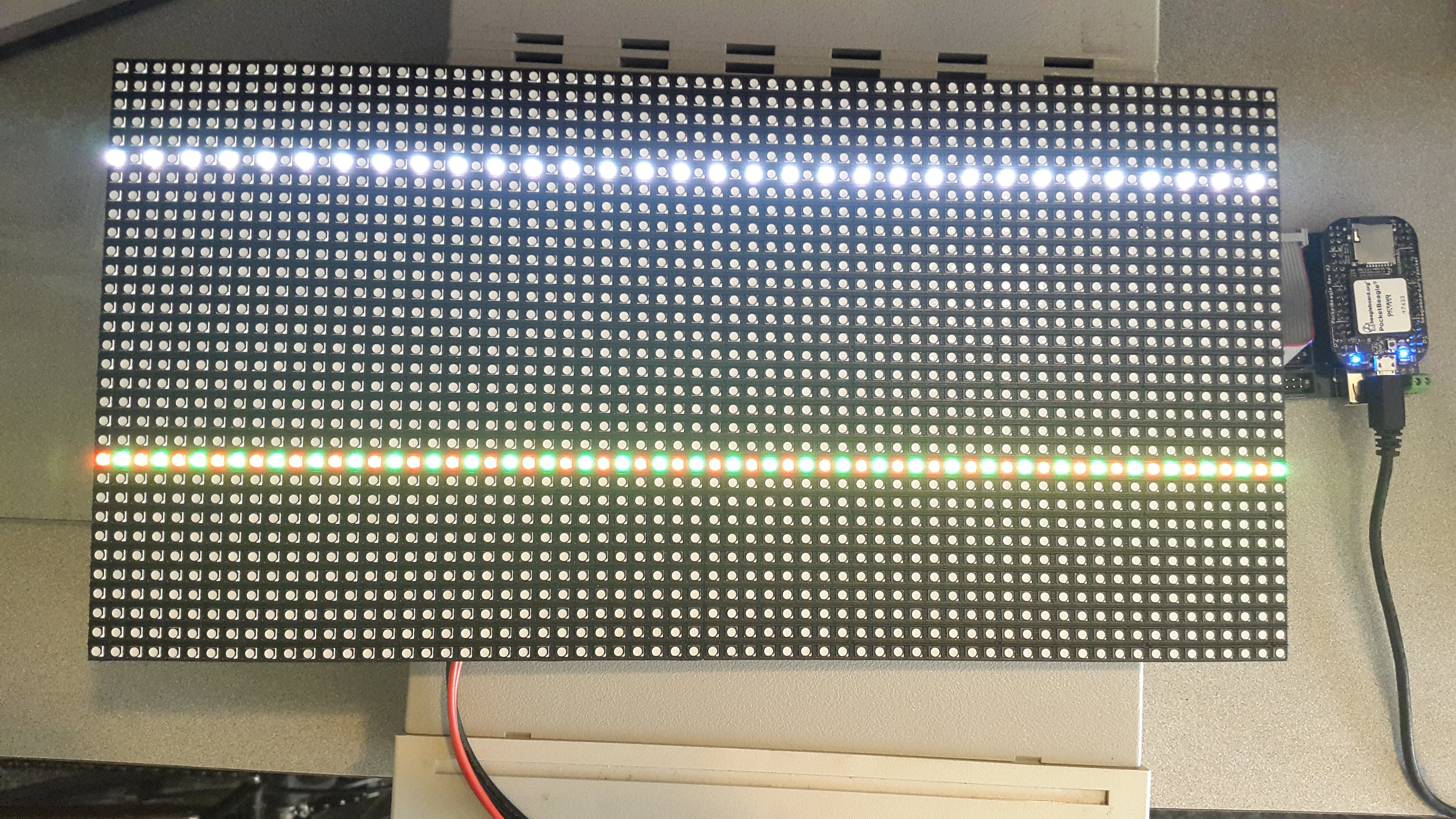
So why do only two lines appear at a time? That’s how the display works. Currently lines 6 and 22 are showing, then a moment later 7 and 23 show, etc. The display can only display two lines at a time, so it cycles through all the lines. Unfortunately, python is too slow to make the display appear all at once. Here’s where the PRU comes in.
PRU code for driving the RGB LED matrix is the PRU code to drive the RGB LED matrix. Be sure to run
bone$ source rgb_setup.sh first.
  1
2
3
4
5
6
7
8
9
10
11
12
13
14
15
16
17
18
19
20
21
22
23
24
25
26
27
28
29
30
31
32
33
34
35
36
37
38
39
40
41
42
43
44
45
46
47
48
49
50
51
52
53
54
55
56
57
58
59
60
61
62
63
64
65
66
67
68
69
70
71
72
73
74
75
76
77
78
79
80

  // This code drives the RGB LED Matrix on the 1st Connector
#include <stdint.h>
#include <pru_cfg.h>
#include "resource_table_empty.h"
#include "prugpio.h"
#include "rgb_pocket.h"

#define DELAY 10    // Number of cycles (5ns each) to wait after a write

volatile register uint32_t R30;
volatile register uint32_t R31;

void main(void)
{
    // Set up the pointers to each of the GPIO ports
    uint32_t *gpio[] = {
            (uint32_t *) GPIO0,
            (uint32_t *) GPIO1,
            (uint32_t *) GPIO2,
            (uint32_t *) GPIO3
        };

    uint32_t i, row;

    while(1) {
        for(row=0; row<16; row++) {
            // Set the row address
            // Here we take advantage of the select bits (LA,LB,LC,LD)
            // being sequential in the R30 register (bits 2,3,4,5)
            // We shift row over so it lines up with the select bits
            // Oring (|=) with R30 sets bits to 1 and
            // Anding (&=) clears bits to 0, the 0xffc mask makes sure the
            // other bits aren't changed.
            R30 |=  row<<pru_sel0;
            R30 &= (row<<pru_sel0)|0xffc3;

            for(i=0; i<64; i++) {
                // Top row white
                // Combining these to one write works because they are all in
                // the same gpio port
                gpio[r11_gpio][GPIO_SETDATAOUT] = r11_pin | g11_pin | b11_pin;
                delay_cycles(DELAY);;

                // Bottom row red
                gpio[r12_gpio][GPIO_SETDATAOUT]   = r12_pin;
                delay_cycles(DELAY);
                gpio[r12_gpio][GPIO_CLEARDATAOUT] = g12_pin | b12_pin;
                delay_cycles(DELAY);

                R30 |=  pru_clock;    // Toggle clock
                delay_cycles(DELAY);
                R30 &= ~pru_clock;
                delay_cycles(DELAY);

                // Top row black
                gpio[r11_gpio][GPIO_CLEARDATAOUT] = r11_pin | g11_pin | b11_pin;
                delay_cycles(DELAY);

                // Bottom row green
                gpio[r12_gpio][GPIO_CLEARDATAOUT] = r12_pin | b12_pin;
                delay_cycles(DELAY);
                gpio[r12_gpio][GPIO_SETDATAOUT]   = g12_pin;
                delay_cycles(DELAY);

                R30 |=  pru_clock;    // Toggle clock
                delay_cycles(DELAY);
                R30 &= ~pru_clock;
                delay_cycles(DELAY);
            }
            R30 |=  pru_oe;        // Disable display
            delay_cycles(DELAY);
            R30 |=  pru_latch;     // Toggle latch
            delay_cycles(DELAY);
            R30 &= ~pru_latch;
            delay_cycles(DELAY);
            R30 &= ~pru_oe;        // Enable display
            delay_cycles(DELAY);
        }
    }
}
The results are shown in Display running rgb1.c on PRU 0.
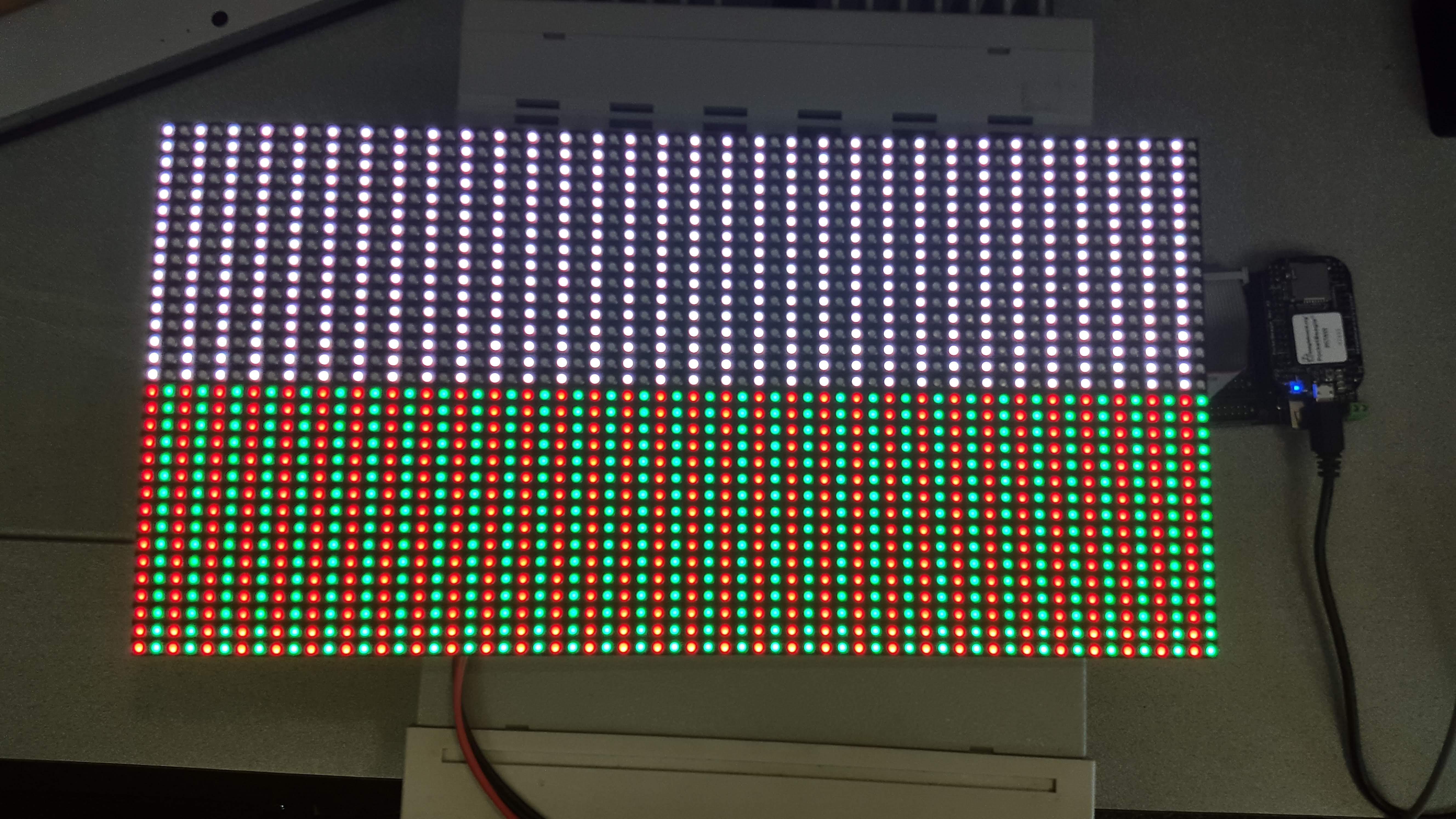
The PRU is fast enough to quickly write to the display so that it appears as if all the LEDs are on at once.
Discussion
There are a lot of details needed to make this simple display work. Let’s go over some of them.
First, the connector looks like RGB Matrix J1 connector.
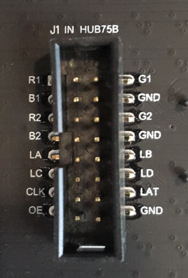
Notice the labels on the connect match the labels in the code. PocketScroller pin table shows how the pins on the display are mapped to the pins on the Pocket Beagle.
| J1 Connector Pin | Pocket Headers | gpio port and bit number | Linux gpio number | PRU R30 bit number |
|---|---|---|---|---|
R1 |
P2_10 |
1-20 |
52 |
|
B1 |
P2_06 |
1-25 |
57 |
|
R2 |
P2_04 |
1-26 |
58 |
|
B2 |
P2_01 |
1-18 |
50 |
|
LA |
P2_32 |
3-16 |
112 |
PRU0.2 |
LC |
P1_31 |
3-18 |
114 |
PRU0.4 |
CLK |
P1_33 |
3-15 |
111 |
PRU0.1 |
OE |
P1_29 |
3-21 |
117 |
PRU0.7 |
G1 |
P2_08 |
1-28 |
60 |
|
G2 |
P2_02 |
1-27 |
59 |
|
LB |
P2_30 |
3-17 |
113 |
PRU0.3 |
LD |
P2_34 |
3-19 |
115 |
PRU0.5 |
LAT |
P1_36 |
3-14 |
110 |
PRU0.0 |
The J1 mapping to gpio port and bit number comes from https://github.com/FalconChristmas/fpp/blob/master/capes/pb/panels/PocketScroller.json. The gpio port and bit number mapping to Pocket Headers comes from https://docs.google.com/spreadsheets/d/1FRGvYOyW1RiNSEVprvstfJAVeapnASgDXHtxeDOjgqw/edit#gid=0.
Oscilloscope display of CLK, OE, LAT and R1 shows four of the signal waveforms driving the RGB LED matrix.
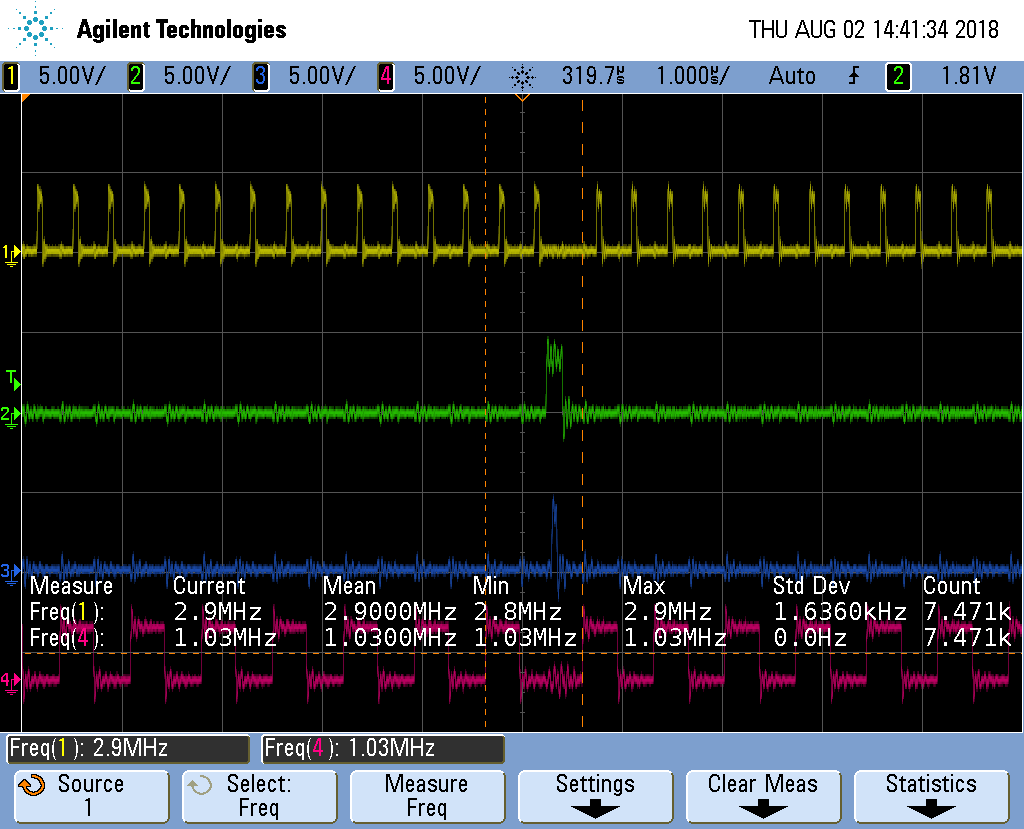
The top waveform is the CLK, the next is OE, followed by LAT and finally R1. The OE (output enable) is active low, so most of the time the display is visible. The sequence is:
-
Put data on the R1, G1, B1, R2, G2 and B2 lines
-
Toggle the clock.
-
Repeat the first two steps as one row of data is transfered. There are 384 LEDs (2 rows of 32 RGB LEDs times 3 LED per RGB), but we are clocking in six bits (R1, G1, etc.) at a time, so 384/6=64 values need to be clocked in.
-
Once all the values are in, disable the display (OE goes high)
-
Then toggle the latch (LAT) to latch the new data.
-
Turn the display back on.
-
Increment the address lines (LA, LB, LC and LD) to point to the next rows.
-
Keep repeating the above to keep the display lit.
Using the PRU we are able to run the clock a about 2.9 MKHz. FPP waveforms shows the optimized assembler code used by FPP clocks in at some 6.3 MHz. So the compiler is doing a pretty good job, but you can run some two times faster if you want to use assembly code. In fairness to FPP, it’s having to pull it’s data out of RAM to display it, so isn’t not a good comparision.
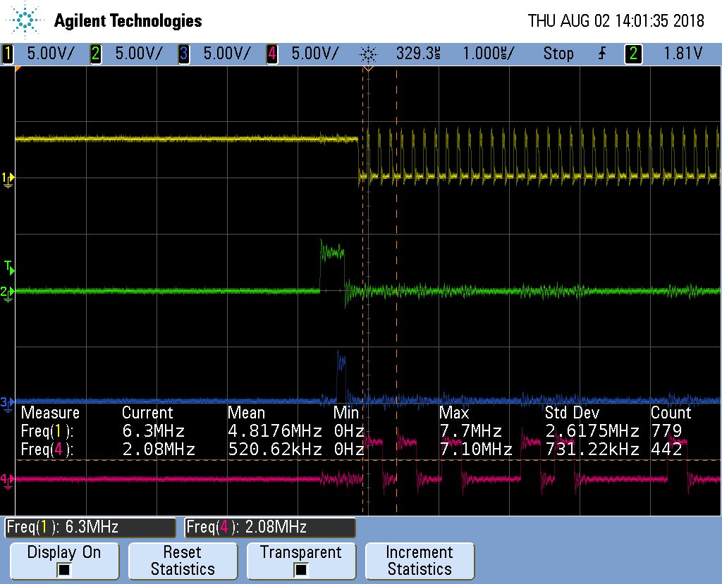
Getting More Colors
The Adafruit description goes on to say:
The only downside of this technique is that despite being very simple and fast, it has no PWM control built-in! The controller can only set the LEDs on or off. So what do you do when you want full color? You actually need to draw the entire matrix over and over again at very high speeds to PWM the matrix manually. For that reason, you need to have a very fast controller (50 MHz is a minimum) if you want to do a lot of colors and motion video and have it look good.
This is what FPP does, but it’s beyond the scope of this project.
1.16. Compiling and Inserting rpmsg_pru
Problem
Your Beagle doesn’t have rpmsg_pru.
Solution
Do the following.
bone$ cd 05blocks/code/module
bone$ sudo apt install linux-headers-`uname -r`
bone$ wget https://github.com/beagleboard/linux/raw/4.9/drivers/rpmsg/rpmsg_pru.c
bone$ make
make -C /lib/modules/4.9.88-ti-r111/build M=$PWD
make[1]: Entering directory '/usr/src/linux-headers-4.9.88-ti-r111'
  LD      /home/debian/PRUCookbook/docs/05blocks/code/module/built-in.o
  CC [M]  /home/debian/PRUCookbook/docs/05blocks/code/module/rpmsg_client_sample.o
  CC [M]  /home/debian/PRUCookbook/docs/05blocks/code/module/rpmsg_pru.o
  Building modules, stage 2.
  MODPOST 2 modules
  CC      /home/debian/PRUCookbook/docs/05blocks/code/module/rpmsg_client_sample.mod.o
  LD [M]  /home/debian/PRUCookbook/docs/05blocks/code/module/rpmsg_client_sample.ko
  CC      /home/debian/PRUCookbook/docs/05blocks/code/module/rpmsg_pru.mod.o
  LD [M]  /home/debian/PRUCookbook/docs/05blocks/code/module/rpmsg_pru.ko
make[1]: Leaving directory '/usr/src/linux-headers-4.9.88-ti-r111'
bone$ sudo insmod rpmsg_pru.ko
bone$ lsmod | grep rpm
rpmsg_pru               5799  2
virtio_rpmsg_bus       13620  0
rpmsg_core              8537  2 rpmsg_pru,virtio_rpmsg_bus
It’s now installed and ready to go.
1.17. Copyright
  1
2
3
4
5
6
7
8
9
10
11
12
13
14
15
16
17
18
19
20
21
22
23
24
25
26
27
28
29
30
31
32

  /*
 * Copyright (C) 2015 Texas Instruments Incorporated - http://www.ti.com/
 *
 *
 * Redistribution and use in source and binary forms, with or without
 * modification, are permitted provided that the following conditions
 * are met:
 *
 *  * Redistributions of source code must retain the above copyright
 *    notice, this list of conditions and the following disclaimer.
 *
 *  * Redistributions in binary form must reproduce the above copyright
 *    notice, this list of conditions and the following disclaimer in the
 *    documentation and/or other materials provided with the
 *    distribution.
 *
 *  * Neither the name of Texas Instruments Incorporated nor the names of
 *    its contributors may be used to endorse or promote products derived
 *    from this software without specific prior written permission.
 *
 * THIS SOFTWARE IS PROVIDED BY THE COPYRIGHT HOLDERS AND CONTRIBUTORS
 * "AS IS" AND ANY EXPRESS OR IMPLIED WARRANTIES, INCLUDING, BUT NOT
 * LIMITED TO, THE IMPLIED WARRANTIES OF MERCHANTABILITY AND FITNESS FOR
 * A PARTICULAR PURPOSE ARE DISCLAIMED. IN NO EVENT SHALL THE COPYRIGHT
 * OWNER OR CONTRIBUTORS BE LIABLE FOR ANY DIRECT, INDIRECT, INCIDENTAL,
 * SPECIAL, EXEMPLARY, OR CONSEQUENTIAL DAMAGES (INCLUDING, BUT NOT
 * LIMITED TO, PROCUREMENT OF SUBSTITUTE GOODS OR SERVICES; LOSS OF USE,
 * DATA, OR PROFITS; OR BUSINESS INTERRUPTION) HOWEVER CAUSED AND ON ANY
 * THEORY OF LIABILITY, WHETHER IN CONTRACT, STRICT LIABILITY, OR TORT
 * (INCLUDING NEGLIGENCE OR OTHERWISE) ARISING IN ANY WAY OUT OF THE USE
 * OF THIS SOFTWARE, EVEN IF ADVISED OF THE POSSIBILITY OF SUCH DAMAGE.
 */