1. Case Studies - Introduction
It’s an exciting time to be making projects that use embedded processors. Make:'s Makers' Guide to Boards shows many of the options that are available and groups them into different types. Single board computers (SBCs) generally run Linux on some sort of ARM processor. Examples are the BeagleBoard and the Raspberry Pi. Another type is the microcontroller, of which the Arduino is popular.
The SBCs are used because they have an operating system to manage files, I/O, and schedule when things are run, all while possibly talking to the Internet. Microcontrollers shine when things being interfaced require careful timing and can’t afford to have an OS preempt an operation.
But what if you have a project that needs the flexibility of an OS and the timing of a microcontroller? This is where the BeagleBoard excels since it has both an ARM procssor running Linux and two [1]; Programmable Real-Time Units (PRUs). The PRUs have 32-bit cores which run independently of the ARM processor, therefore they can be programmed to respond quickly to inputs and produce very precisely timed outputs.
There are many projects that use the PRU. They are able to do things that can’t be done with just a SBC or just a microcontroller. Here we present some case studies that give a high-level view of using the PRUs. In later chapters you will see the details of how they work.
Here we present:
-
Robotics Control Library http://strawsondesign.com/docs/roboticscape/
-
BeagleLogic https://github.com/abhishek-kakkar/BeagleLogic/wiki
-
NeoPixels — 5050 RGB LEDs with Integrated Drivers (Falcon Christmas) http://falconchristmas.com
-
RGB LED Matrix (Falcon Christmas) http://falconchristmas.com
-
simpPRU — A python-like language for programming the PRUs https://github.com/VedantParanjape/simpPRU
The following are resources used in this chapter.
1.1. Robotics Control Library
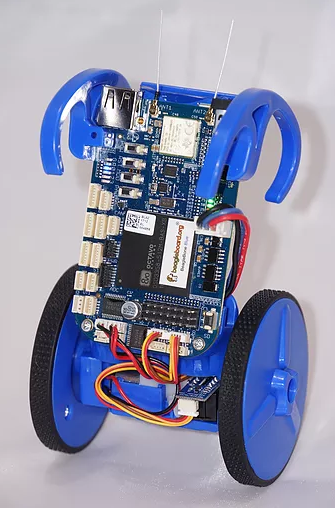
Robotics is an embedded application that often requires both an SBC to control the high-level tasks (such as path planning, line following, communicating with the user) and a microcontroller to handle the low-level tasks (such as telling motors how fast to turn, or how to balance in response to an IMU input). The EduMIP balancing robot demonstrates that by using the PRU, the Blue can handle both the high and low -level tasks without an additional microcontroller. The EduMIP is shown in Blue balancing.
The Robotics Control Library is a package that is already installed on the Beagle that contains a C library and example/testing programs. It uses the PRU to extend the real-time hardware of the Bone by adding eight addional servo channels and one addition real-time encoder input.
The following examples show how easy it is to use the PRU for robotics.
Controlling Eight Servos
Problem
You need to control eight servos, but the Bone doesn’t have enough pulse width modulation (PWM) channels and you don’t want to add hardware.
Solution
The Robotics Control Library provides eight additional PWM channels via the PRU that can be used out of the box.
|
Note
|
The I/O pins on the Beagles have a mutliplexer that lets you select what I/O appears on a given pin. The Blue has the mux already configured to to run these examples. Follow the instructions in Configuring Pins for Controlling Servos to configure the pins for the Black and the Pocket. |
Just run:
bone$ sudo rc_test_servos -f 10 -p 1.5The -f 10 says to use a frequency of 10 Hz and the -p 1.5 says to set the position to 1.5. The range of positions is
-1.5 to 1.5. Run rc_test_servos -h to see all the options.
bone$ rc_test_servos -h

 Options
 -c {channel}   Specify one channel from 1-8.
                Otherwise all channels will be driven equally
 -f {hz}        Specify pulse frequency, otherwise 50hz is used
 -p {position}  Drive servo to a position between -1.5 & 1.5
 -w {width_us}  Send pulse width in microseconds (us)
 -s {limit}     Sweep servo back/forth between +- limit
                Limit can be between 0 & 1.5
 -r {ch}        Use DSM radio channel {ch} to control servo
 -h             Print this help messege

sample use to center servo channel 1:
   rc_test_servo -c 1 -p 0.0
Discussion
The BeagleBone Blue sends these eight outputs to it’s servo channels. The others use the pins shown in the PRU register to pin table.
| PRU pin | Blue pin | Black pin | Pocket pin | AI pin |
|---|---|---|---|---|
pru1_r30_8 |
1 |
P8_27 |
P2.35 |
|
pru1_r30_10 |
2 |
P8_28 |
P1.35 |
P9_42 |
pru1_r30_9 |
3 |
P8_29 |
P1.02 |
P8_14 |
pru1_r30_11 |
4 |
P8_30 |
P1.04 |
P9_27 |
pru1_r30_6 |
5 |
P8_39 |
P8_19 |
|
pru1_r30_7 |
6 |
P8_40 |
P8_13 |
|
pru1_r30_4 |
7 |
P8_41 |
||
pru1_r30_5 |
8 |
P8_42 |
P8_18 |
You can find these details in the P8 Header Table, P9 Header Table, Pocket Beagle System Reference Manual (Here is a more usable version of the table.) and BeagleBone AI System Reference Manual. (Here is a more usable version of the table.)
Be default the PRUs are already loaded with the code needed to run the servos. All you have to do is run the command.
Controlling Individual Servos
Problem
rc_test_servos is nice, but I need to control the servos individually.
Solution
You can modify rc_test_servos.c. You’ll find it on the bone online at
<https://github.com/beagleboard/librobotcontrol/blob/master/examples/src/rc_test_servos.c.
Just past line 250 you’ll find a while loop that has calls to rc_servo_send_pulse_normalized(ch,servo_pos) and
rc_servo_send_pulse_us(ch, width_us). The first call sets the pulse width relative to the pulse period; the other
sets the width to an absolute time. Use whichever works for you.
Controlling More Than Eight Channels
Problem
I need more than eight PWM channels, or I need less jitter on the off time.
Solution
This is a more advanced problem and required reprograming the PRUs. See PWM Generator for an example.
Reading Hardware Encoders
Problem
I want to use four encoders to measure four motors, but I only see hardware for three.
Solution
The forth encoder can be implemented on the PRU. If you run rc_test_encoders_eqep on the Blue, you will see the output of
encoders E1-E3 which are connected to the eEQP hardware.
bone$ rc_test_encoders_eqep

Raw encoder positions
      E1   |      E2   |      E3   |
         0 |         0 |         0 |^C
You can also access these hardware encoders on the Black and Pocket using the pins shown in eQEP to pin mapping.
| eQEP | Blue pin | Black pin A | Black pin B | AI pin A | AI pin B | Pocket pin A | Pocket pin B |
|---|---|---|---|---|---|---|---|
0 |
E1 |
P9_42B |
P9_27 |
P1.31 |
P2.24 |
||
1 |
E2 |
P8_35 |
P8_33 |
P8_35 |
P8_33 |
P2.10 |
|
2 |
E3 |
P8_12 |
P8_11 |
P8_12 |
P8_11 |
P2.24 |
P2.33 |
2 |
P8_41 |
P8_42 |
P9_19 |
P9_41 |
|||
E4 |
P8_16 |
P8_15 |
P2.09 |
P2.18 |
|||
3 |
P8_25 |
P8_24 |
|||||
3 |
P9_42 |
P9_27 |
|
Note
|
The I/O pins on the Beagles have a mutliplexer that lets you select what I/O appears on a given pin. The Blue has the mux already configured to to run these examples. Follow the instructions in Configuring Pins for Controlling Encoders to configure the pins for the Black and the Pocket. |
Reading PRU Encoder
Problem
I want to access the PRU encoder.
Solution
The forth encoder is implemented on the PRU and accessed with sudo rc_test_encoders_pru
|
Note
|
This command
needs root permission, so the |
Here’s what you will see
bone$ sudo rc_test_encoders_pru
[sudo] password for debian:

Raw encoder position
      E4   |
0 |^C|
Note
|
If you aren’t running the Blue you will have to configure the pins as shown in the note above. |
1.2. BeagleLogic — a 14-channel Logic Analyzer
Problem
I need a 100Msps, 14-channel logic analyzer
Solution
BeagleLogic is a 100Msps, 14-channel logic analyzer that runs on the Beagle.
BeagleLogic turns your BeagleBone [Black] into a 14-channel, 100Msps Logic Analyzer. Once loaded, it presents itself as a character device node /dev/beaglelogic.

The core of the logic analyzer is the 'beaglelogic' kernel module that reserves memory for and drives the two Programmable Real-Time Units (PRU) via the remoteproc interface wherein the PRU directly writes logic samples to the System Memory (DDR RAM) at the configured sample rate one-shot or continuously without intervention from the ARM core.
The quickest solution is to get the no-setup-required image. It points to an older image (beaglelogic-stretch-2017-07-13-4gb.img.xz ) but should still work.
If you want to be running a newer image, there are instructions on the site for installing BeagleLogic, but I had to do the additional steps in Installing BeagleLogic.
bone$ git clone https://github.com/abhishek-kakkar/BeagleLogic
bone$ cd BeagleLogic/kernel
bone$ mv beaglelogic-00A0.dts beaglelogic-00A0.dts.orig
bone$ wget https://gist.githubusercontent.com/abhishek-kakkar/0761ef7b10822cff4b3efd194837f49c/raw/eb2cf6cfb59ff5ccb1710dcd7d4a40cc01cfc050/beaglelogic-00A0.dts
bone$ make overlay
bone$ sudo cp beaglelogic-00A0.dtbo /lib/firmware/
bone$ sudo update-initramfs -u -k `uname -r`
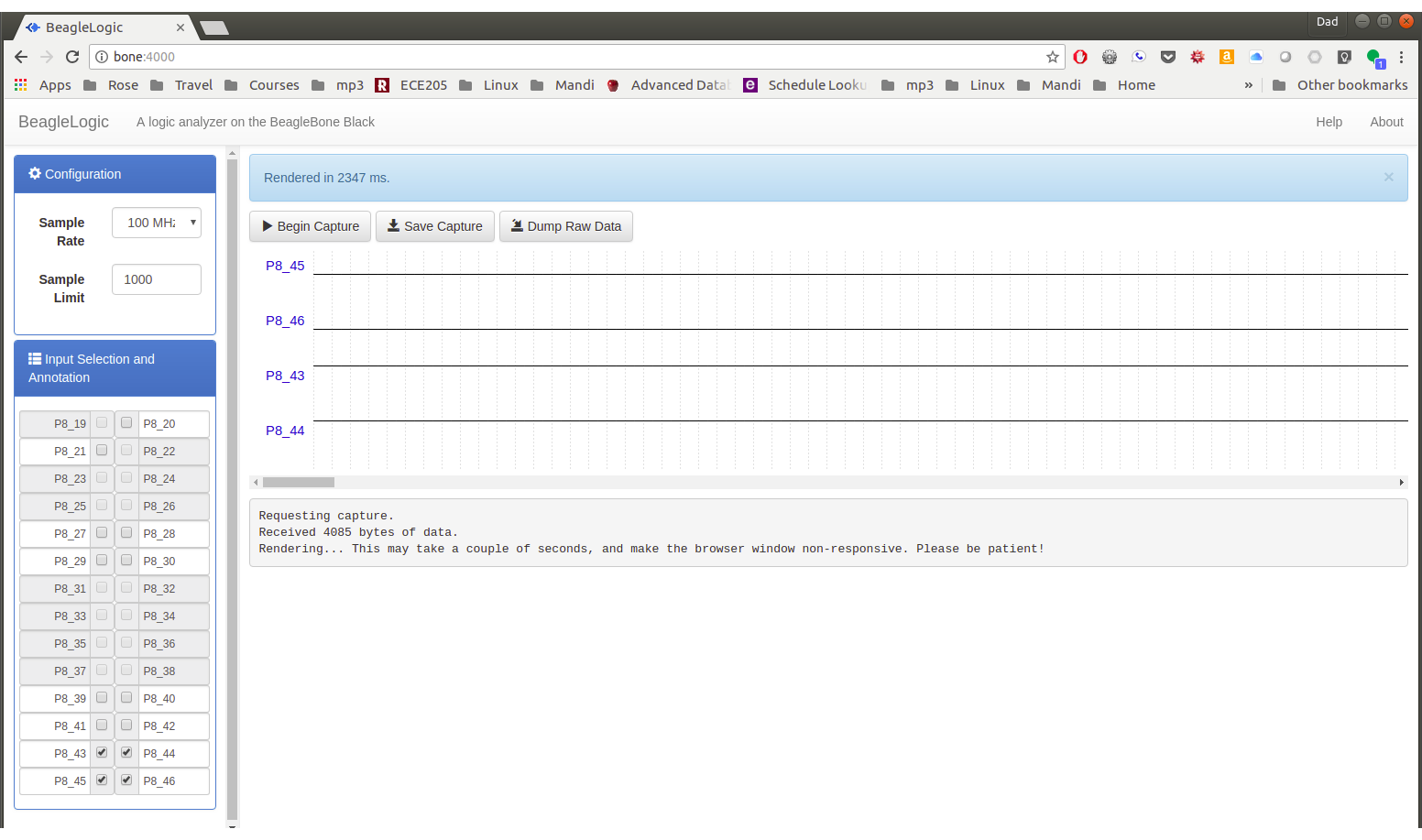
bone$ sudo rebootOnce the Bone has rebooted, browse to 192.168.7.2:4000 where you’ll see BeagleLogic Data Capture. Here you can easily select the sample rate, number of samples, and which pins to sample. Then click Begin Capture to capture your data, at up to 100 MHz!
Discussion
BeagleLogic is a complete system that includes firmware for the PRUs, a kernel module and a web interface that create a powerful 100 MHz logic analyzer on the Bone with no additional hardware needed.
|
Tip
|
If you need buffered inputs, consider BeagleLogic Standalone, a turnkey Logic Analyzer built on top of BeagleLogic. |
The kernel interface makes it easy to control the PRUs through the command line. For example
bone$ dd if=/dev/beaglelogic of=mydump bs=1M count=1
will capture a binary dump from the PRUs. The sample rate and number of
bits per sample can be controlled through /sys/.
bone$ cd /sys/devices/virtual/misc/beaglelogic
bone$ ls
buffers      filltestpattern  power       state         uevent
bufunitsize  lasterror        samplerate  subsystem
dev          memalloc         sampleunit  triggerflags
bone$ cat samplerate
1000
bone$ cat sampleunit
8bit
You can set the sample rate by simply writing to samplerate.
bone$ echo 100000000 > samplerate
sysfs attributes Reference has more details on configuring via sysfs.
If you run dmesg -Hw in another window you can see when a capture
is started and stopped.
bone$ dmesg -Hw
[Jul25 08:46] misc beaglelogic: capture started with sample rate=100000000 Hz, sampleunit=1, triggerflags=0
[  +0.086261] misc beaglelogic: capture session ended
BeagleLogic uses the two PRUs to sample at 100Msps. Getting a PRU running at 200Hz to sample at 100Msps is a slick trick. The Embedded Kitchen has a nice article explaining how the PRUs get this type of performance.
1.3. NeoPixels — 5050 RGB LEDs with Integrated Drivers (Falcon Christmas)
Problem
You have an Adafruit NeoPixel LED string, Adafruit NeoPixel LED matrix or any other type of WS2812 LED and want to light it up.
Solution
If you are driving just one string you can write your own code (See WS2812 Driver) If you plan to drive multiple strings, then consider Falcon Christmas (FPP, <<https://falconchristmas.com/>>). FPP can be used to drive both LEDs with an integrated driver (neopixels) or without an integrated driver. Here we’ll show you how to set up for the integrated drive and in the next section the no driver LEDs will be show.
Hardware
For this setup we’ll wire a single string of NeoPixels to the Beagle. I’ve attached the black wire on the string to ground on the Beagle and the red wire to a 3.3V pin on the Beagle. The yellow data in line is attached to P1.31 (I’m using a PocketBeagle.).
How did I know to attach to P1.31? The FalconChristmas git repo (https://github.com/FalconChristmas/fpp) has files that tell which pins attach to which port. https://github.com/FalconChristmas/fpp/blob/master/capes/pb/strings/F8-B-20.json has a list of 20 ports and where they are connected. Pin P1.31 appears on line 27. It’s the 20th entry in the list. You could pick any of the others if you’d rather.
Software Setup
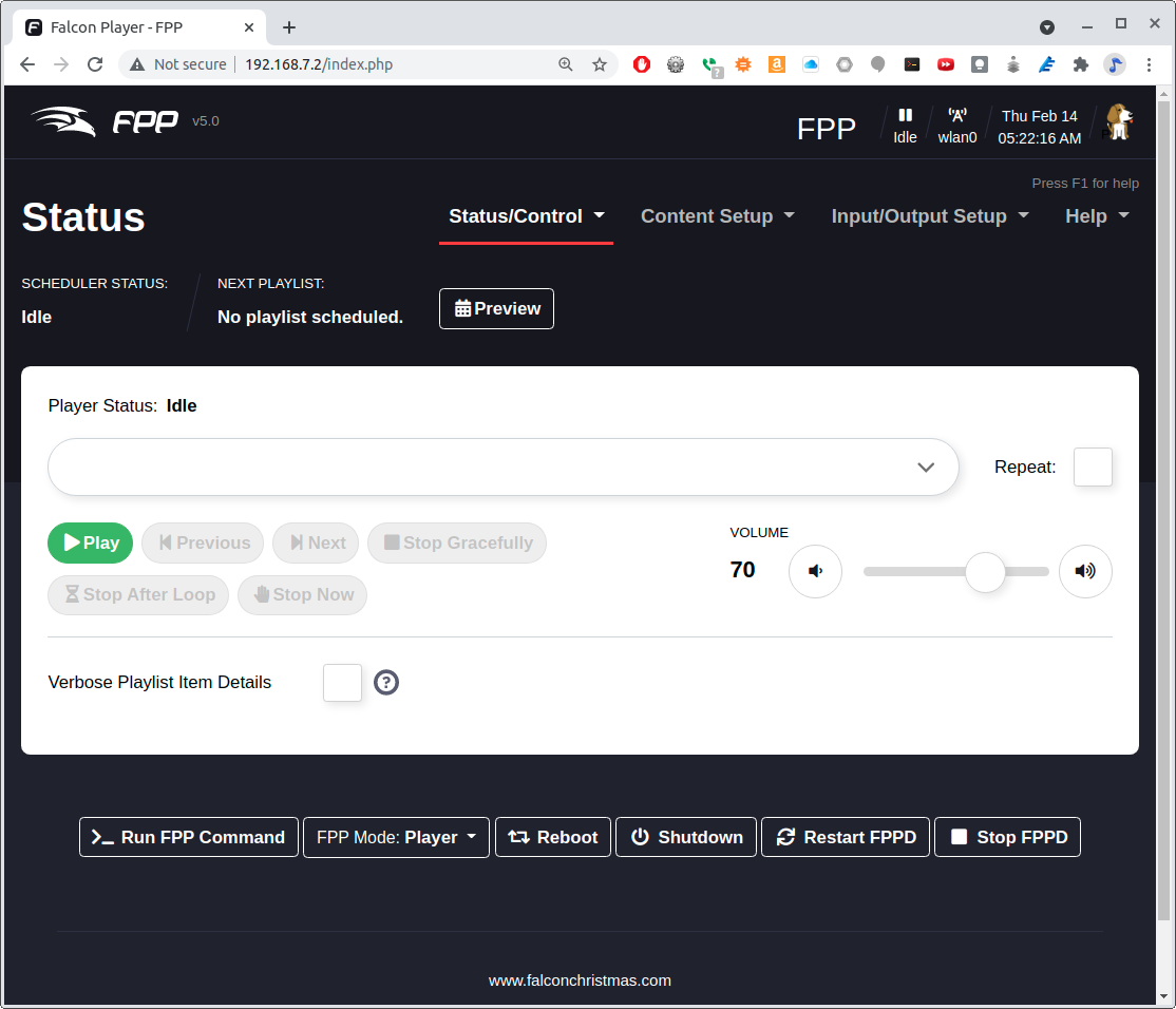
Assuming the PocketBeagle is attached via the USB cable, on your host computer browse to http://192.168.7.2/ and you will see Falcon Play Program Control.
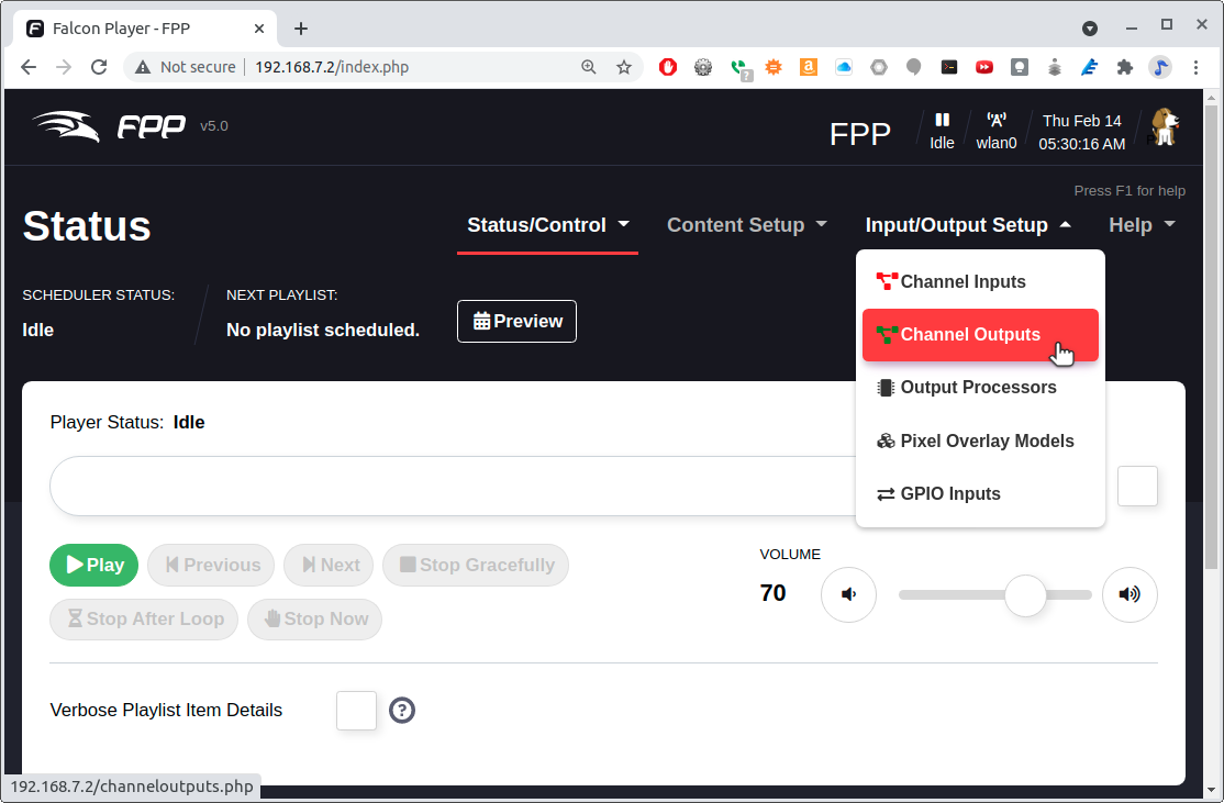
You can test the display by first setting up the Channel Outputs and then going to Display Testing. Selecting Channel Outputs shows where to select Channel Outputs and Channel Outputs Settings shows which settings to use.
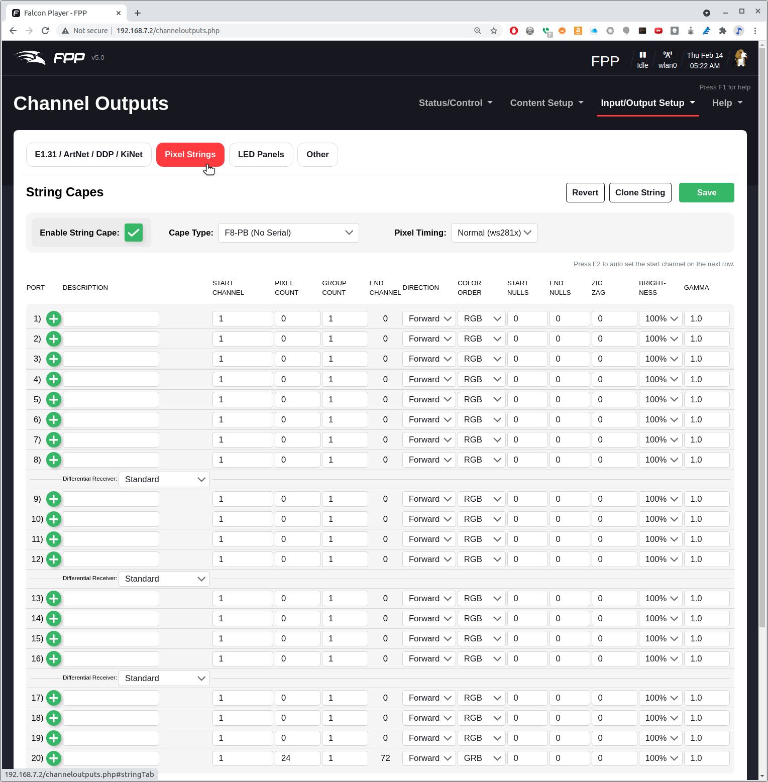
Click on the Pixel Strings tab. Earlier we noted that P1.31 is attached to port 20. Note that at the bottom of the screen, port 20 has a PIXEL COUNT of 24. We’re telling FPP our string has 24 NeoPixels and they are attached to port 2 which in P1.31.
Be sure to check the Enable String Cape.
Next we need to test the display. Select Display Testing shown in Selecting Display Testing.
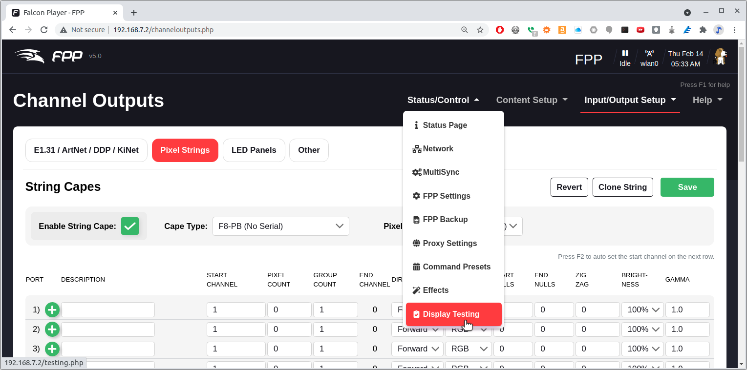
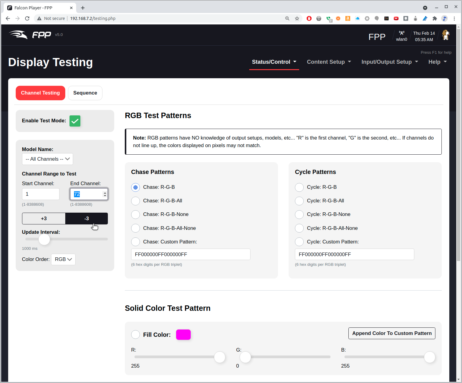
Set the End Channel to 72. (72 is 3*24) Click Enable Test Mode and your matrix should light up. Try the different testing patterns shown in Display Testing Options.
|
Note
|
Clicking on the -3 will subtract three from the End Channel, which should then display three fewer LEDs which is one NeoPixel. The last of your NeoPixels should go black. This is an easy way to make sure you have the correct pixel count. |
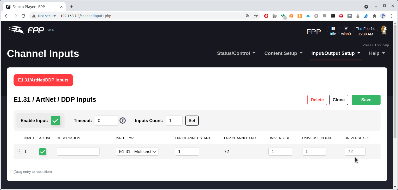
You can control the LED string using the E1.31 protocol. (https://www.doityourselfchristmas.com/wiki/index.php?title=E1.31_(Streaming-ACN)_Protocol) First configure the input channels by going to Channel Inputs as shown in Going to Channel Inputs.
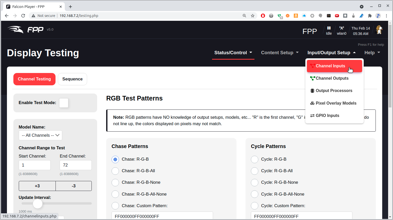
Tell it you have 72 LEDs and enable the input as shown in Setting Channel Inputs.
Finally go to the Status Page as shown in Watching the status.
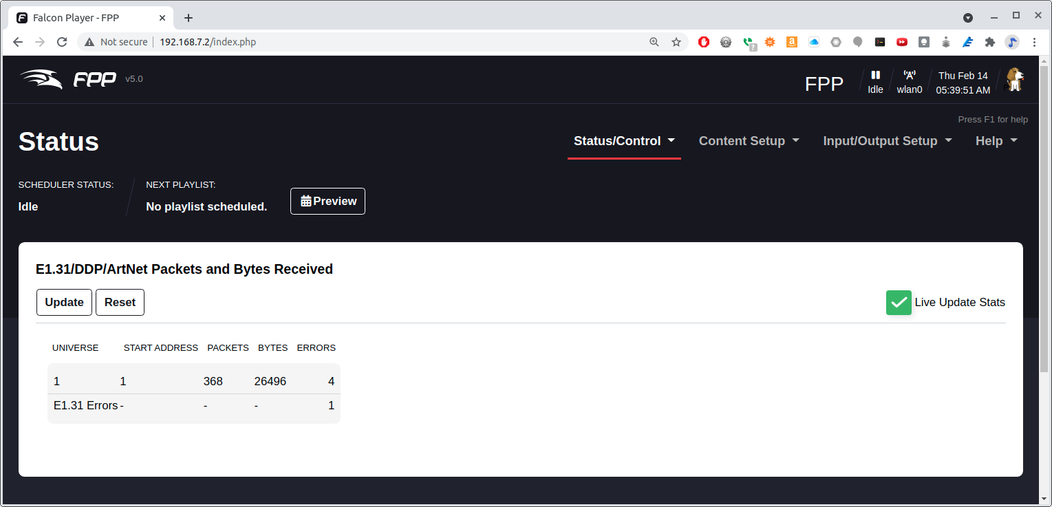
Now run a program on another computer that generated E1.31 packets. [case_1.31_example] is an example python program.
  1
2
3
4
5
6
7
8
9
10
11
12
13
14
15
16
17
18
19
20
21
22
23
24
25
26
27
28
29
30
31
32
33
34
35
36
37
38
39
40
41
42
43
44
45
46
47
48
49
50
51
52
53
54
55
56
57
58
59
60
61
62
63
64
65
66
67
68
69
70

  !/usr/bin/env python3
 Controls a NeoPixel (WS2812) string via E1.31 and FPP
# https://pypi.org/project/sacn/
# https://github.com/FalconChristmas/fpp/releases
import sacn
import time

# provide an IP-Address to bind to if you are using Windows and want to use multicast
sender = sacn.sACNsender("192.168.7.1")
sender.start()                          # start the sending thread
sender.activate_output(1)       # start sending out data in the 1st universe
sender[1].multicast = False # set multicast to True
sender[1].destination = "192.168.7.2"  # or provide unicast information.
sender.manual_flush = True # turning off the automatic sending of packets
# Keep in mind that if multicast is on, unicast is not used
LEDcount = 24
# Have green fade is as it goes
data = []
for i in range(LEDcount):
    data.append(0)      # Red
    data.append(i)      # Green
    data.append(0)      # Blue
sender[1].dmx_data = data
sender.flush()
time.sleep(0.5)

# Turn off all LEDs
data=[]
for i in range(3*LEDcount):
    data.append(0)
sender.flush()
sender[1].dmx_data = data
time.sleep(0.5)

# Have red fade in
data = []
for i in range(LEDcount):
    data.append(i)
    data.append(0)
    data.append(0)
sender[1].dmx_data = data
sender.flush()
time.sleep(0.25)

# Make LED circle 5 times
for j in range(15):
    for i in range(LEDcount-1):
        data[3*i+0] = 0
        data[3*i+1] = 0
        data[3*i+2] = 0
        data[3*i+3] = 0
        data[3*i+4] = 64
        data[3*i+5] = 0
        sender[1].dmx_data = data
        sender.flush()
        time.sleep(0.02)
# Wrap around
    i = LEDcount-1
    data[0] = 0
    data[1] = 64
    data[2] = 0
    data[3*i+0] = 0
    data[3*i+1] = 0
    data[3*i+2] = 0
    sender[1].dmx_data = data
    sender.flush()
    time.sleep(0.02)

time.sleep(2)  # send the data for 10 seconds
sender.stop()  # do not forget to stop the sender
1.4. RGB LED Matrix — No Integrated Drivers (Falcon Christmas)
Problem
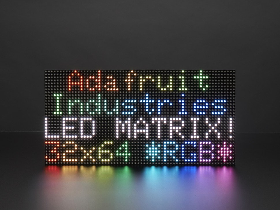
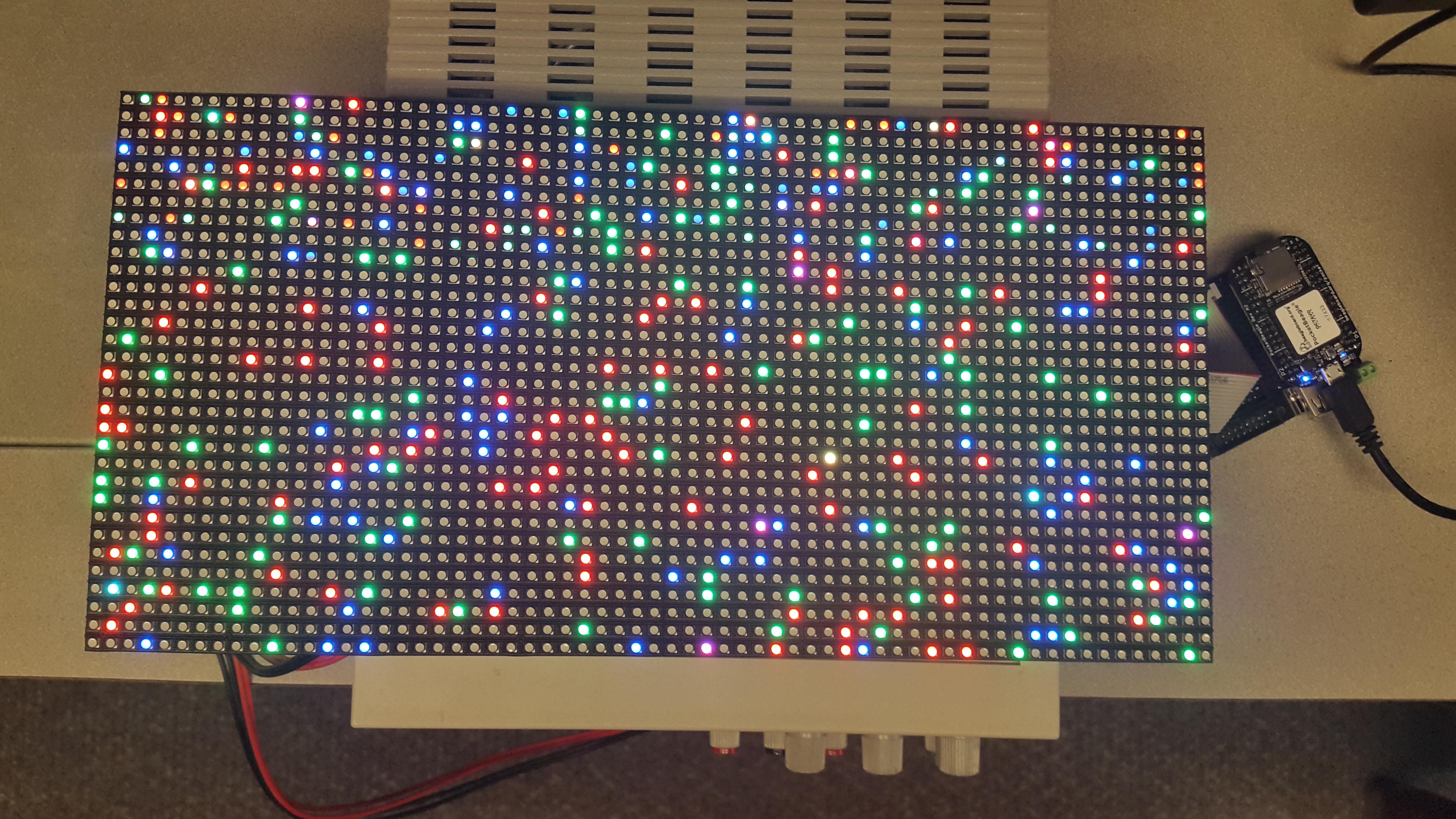
You want to use a RGB LED Matrix display that doesn’t have integrated drivers such as the 64x32 RGB LED Matrix by Adafuit shown in Adafruit LED Matrix.
Solution
Falcon Christmas makes a software package called Falcon Player (FPP) which can drive such displays.
The Falcon Player (FPP) is a lightweight, optimized, feature-rich sequence player
designed to run on low-cost SBC’s (Single Board Computers).
FPP is a software solution that you download and install on hardware which can be
purchased from numerous sources around the internet.
FPP aims to be controller agnostic, it can talk E1.31, DMX, Pixelnet, and
Renard to hardware from multiple hardware vendors, including controller
hardware from Falcon Christmas available via COOPs or in the store on FalconChristmas.com.
Hardware
The Beagle hardware can be either a BeagleBone Black with the Octoscroller Cape, or a PocketBeagle with the PocketScroller LED Panel Cape. (See to purchase.) Building and Octoscroller Matrix Display gives details for using the BeagleBone Black.
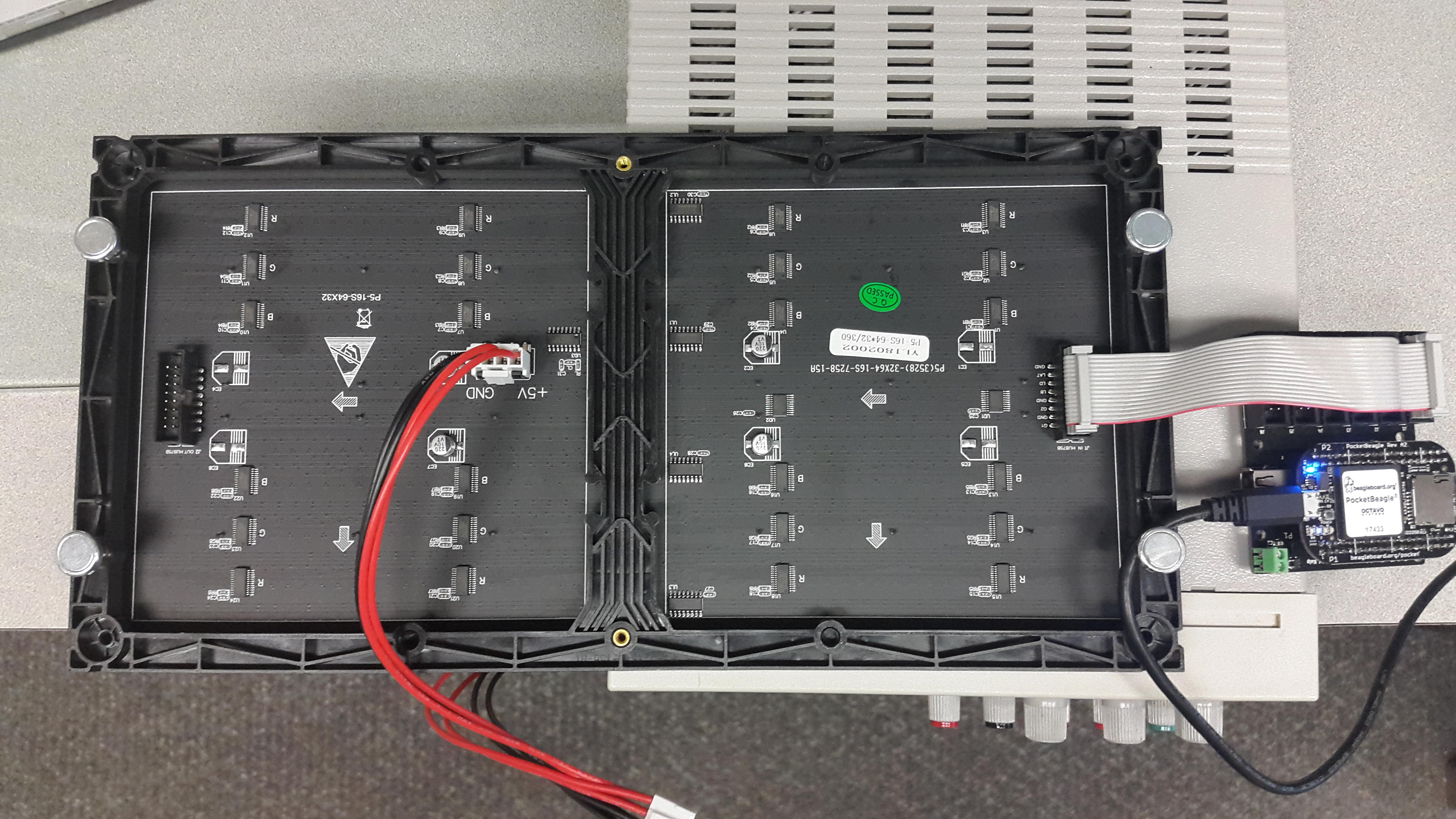
Pocket Beagle Driving a P5 RGB LED Matrix via the PocketScroller Cape shows how to attach the PocketBeagle to the P5 LED matrix and where to attach the 5V power. If you are going to turn on all the LEDs to full white at the same time you will need at least a 4A supply.
Software
The FPP software is most easily installed by downloading the current FPP release, flashing an SD card and booting from it.
|
Tip
|
The really brave can install it on a already running image. See details at https://github.com/FalconChristmas/fpp/blob/master/SD/FPP_Install.sh |
Assuming the PocketBeagle is attached via the USB cable, on your host computer browse to http://192.168.7.2/ and you will see Falcon Play Program Control.
You can test the display by first setting up the Channel Outputs and then going to Display Testing. Selecting Channel Outputs shows where to select Channel Outputs and Channel Outputs Settings shows which settings to use.
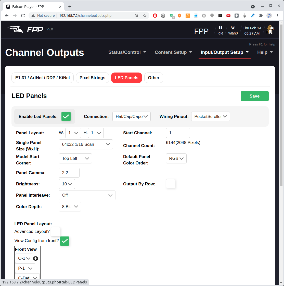
Click on the LED Panels tab and then the only changes I made was to select the Single Panel Size to be 64x32 and to check the Enable LED Panel Output.
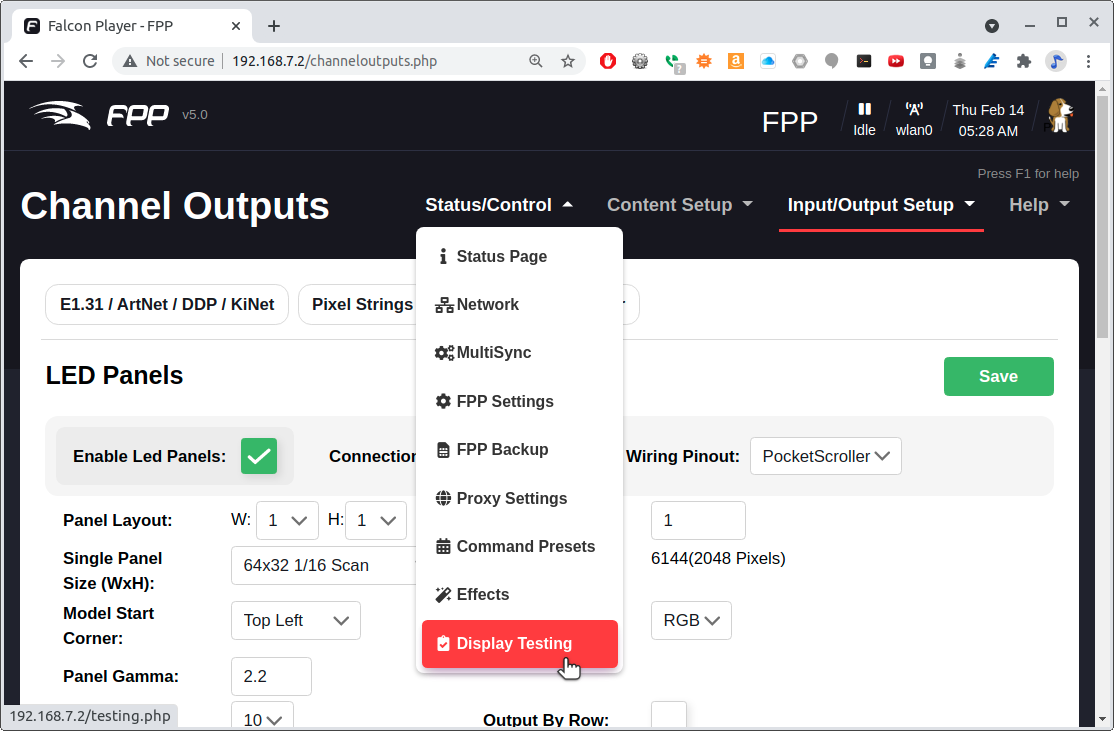
Next we need to test the display. Select Display Testing shown in Selecting Display Testing.
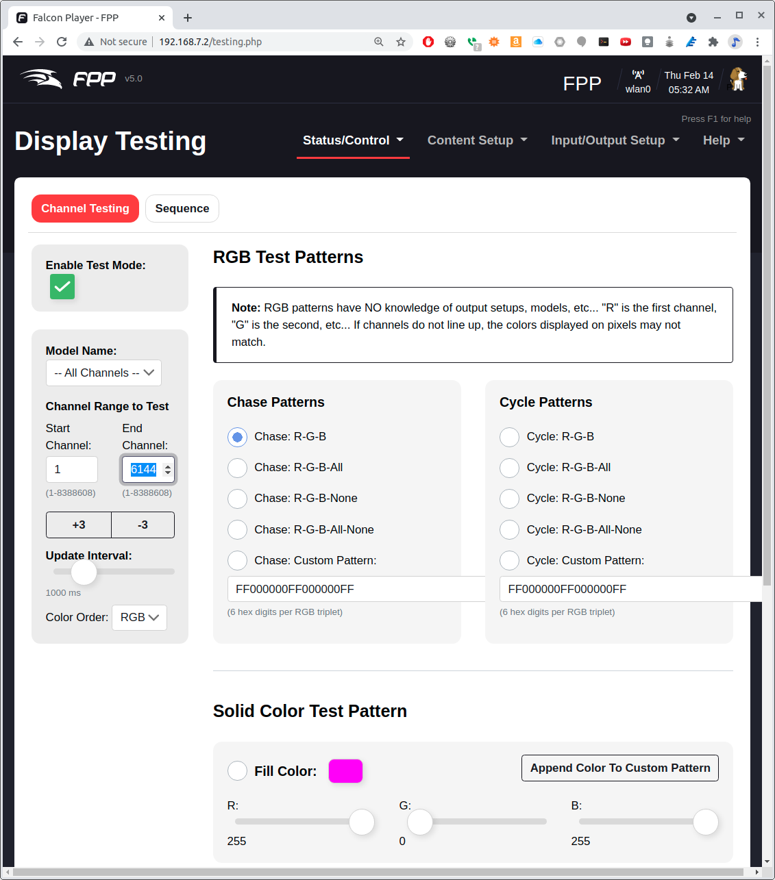
Set the End Channel to 6144. (6144 is 3*64*32) Click Enable Test Mode and your matrix should light up. Try the different testing patterns shown in Display Testing Options.
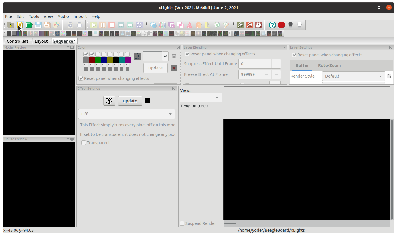
xLights - Creating Content for the Display
Once you are sure your LED Matrix is working correctly you can program it with a sequence.
xLights is a free and open source program that enables you to design, create and play amazing lighting displays through the use of DMX controllers, E1.31 Ethernet controllers and more.

With it you can layout your display visually then assign effects to the various items throughout your sequence. This can be in time to music (with beat-tracking built into xLights) or just however you like.
xLights runs on Windows, OSX and Linux
xLights can be installed on your host computer (not the Beagle) by following instructions at https://xlights.org/releases/.
Run xLights and you’ll see xLights Setup.
host$ chmod +x xLights-2021.18-x86_64.AppImage
host$ ./xLights-2021.18-x86_64.AppImage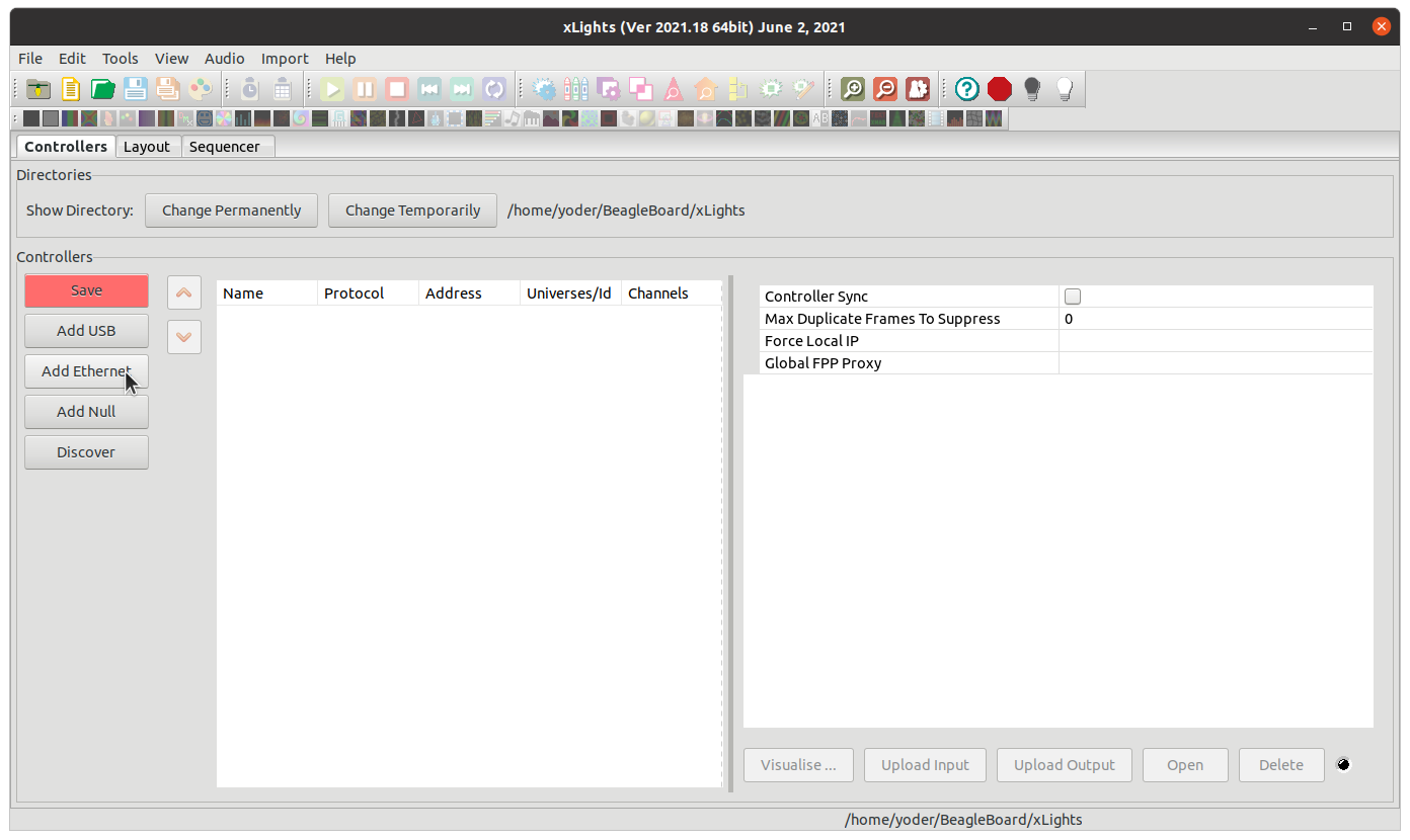
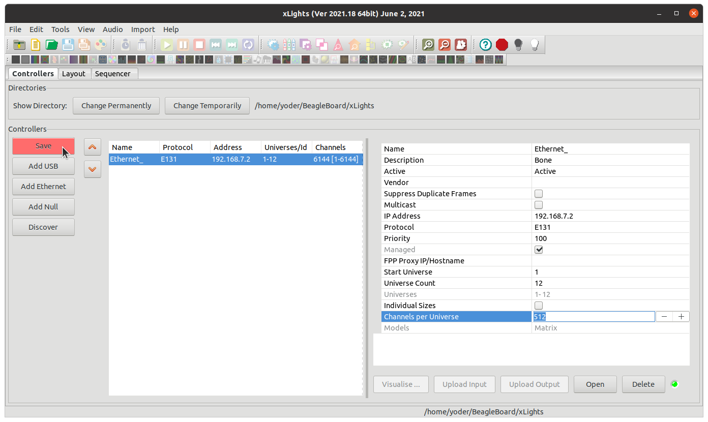
We’ll walk you through a simple setup to get an animation to display on the RGB Matrix. xLights can use a protocol called E1.31 to send information to the display. Setup xLights by clicking on Add Ethernet and entering the values shown in Setting Up E1.31.
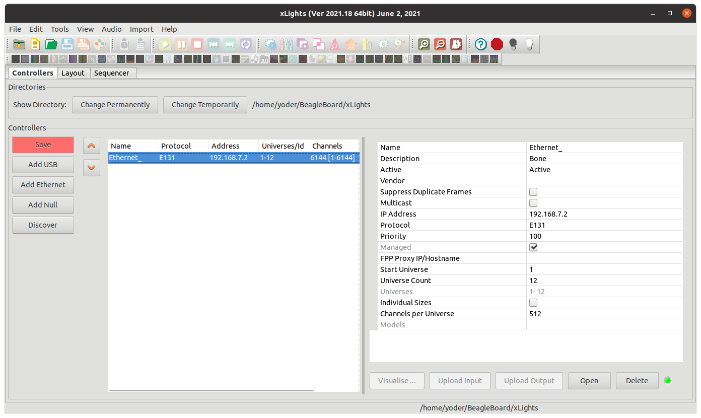
The IP Address is the Bone’s address as seen from the host computer. Each LED is one channel, so one RGB LED is three channels. The P5 board has 3*64*32 or 6144 channels. These are grouped into universes of 512 channels each. This gives 6144/512 = 12 universes. See the E.13 documentation for more details.
Your setup should look like xLights setup for P5 display. Click the Save Setup button to save.
Next click on the Layout tab. Click on the Matrix button as shown in Setting up the Matrix Layout, then click on the black area where you want your matrix to appear.
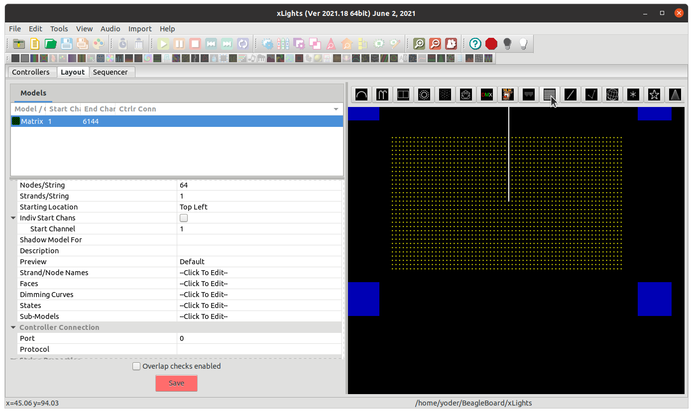
Layout details for P5 matrix shows the setting to use for the P5 matrix.
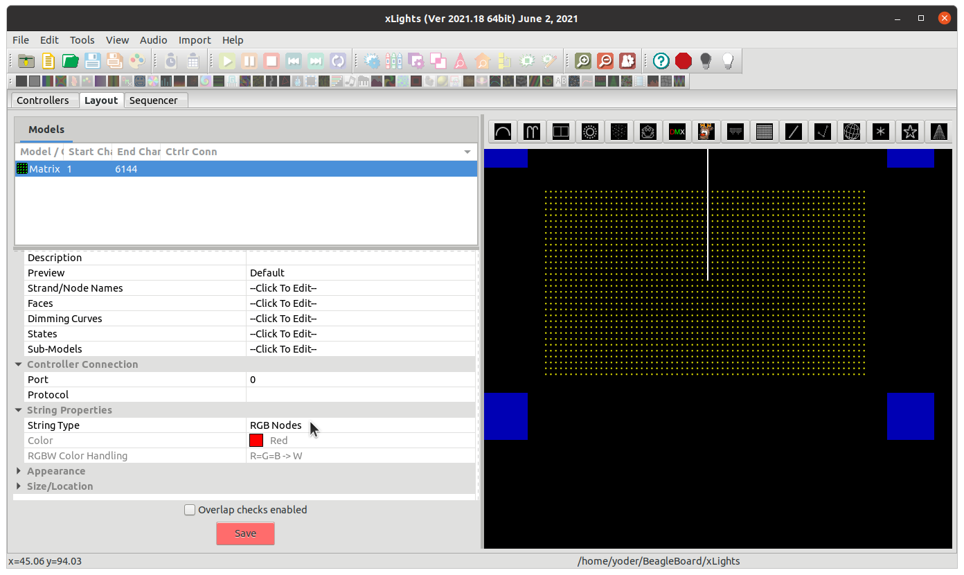
All I changed was # Strings, Nodes/String, Starting Location and most importantly, expand String Properties and select at String Type of RGB Nodes. Above the setting you should see that Start Chan is 1 and the End Chan is 6144, which is the total number of individual LEDs (3*63*32). xLights now knows we are working with a P5 matrix, now on to the sequencer.
Now click on the Sequencer tab and then click on the New Sequence button (Starting a new sequence).
Then click on Animation, 20fps (50ms), and Quick Start. Learning how to do sequences is beyond the scope of this cookbook, however I’ll shown you how do simple sequence just to be sure xLights is talking to the Bone.
Setting Up E1.31 on the Bone
First we need to setup FPP to take input from xLights. Do this by going to the Input/Output Setup menu and selecting Channel Inputs. Then enter 12 for Universe Count and click set and you will see E1.31 Inputs.
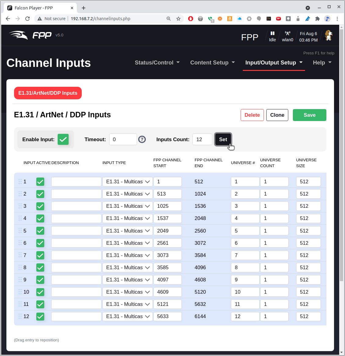
Click on the Save button above the table.
Then go to the Status/Control menu and select Status Page.
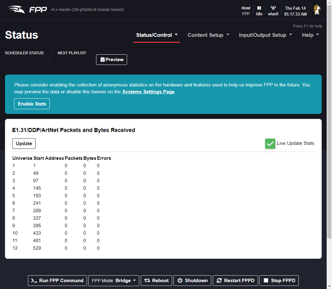
Testing the xLights Connection
The Bone is now listening for commands from xLights via the E1.31 protocol. A quick way to verify everything is t o return to xLights and go to the Tools menu and select Test (xLights test page).
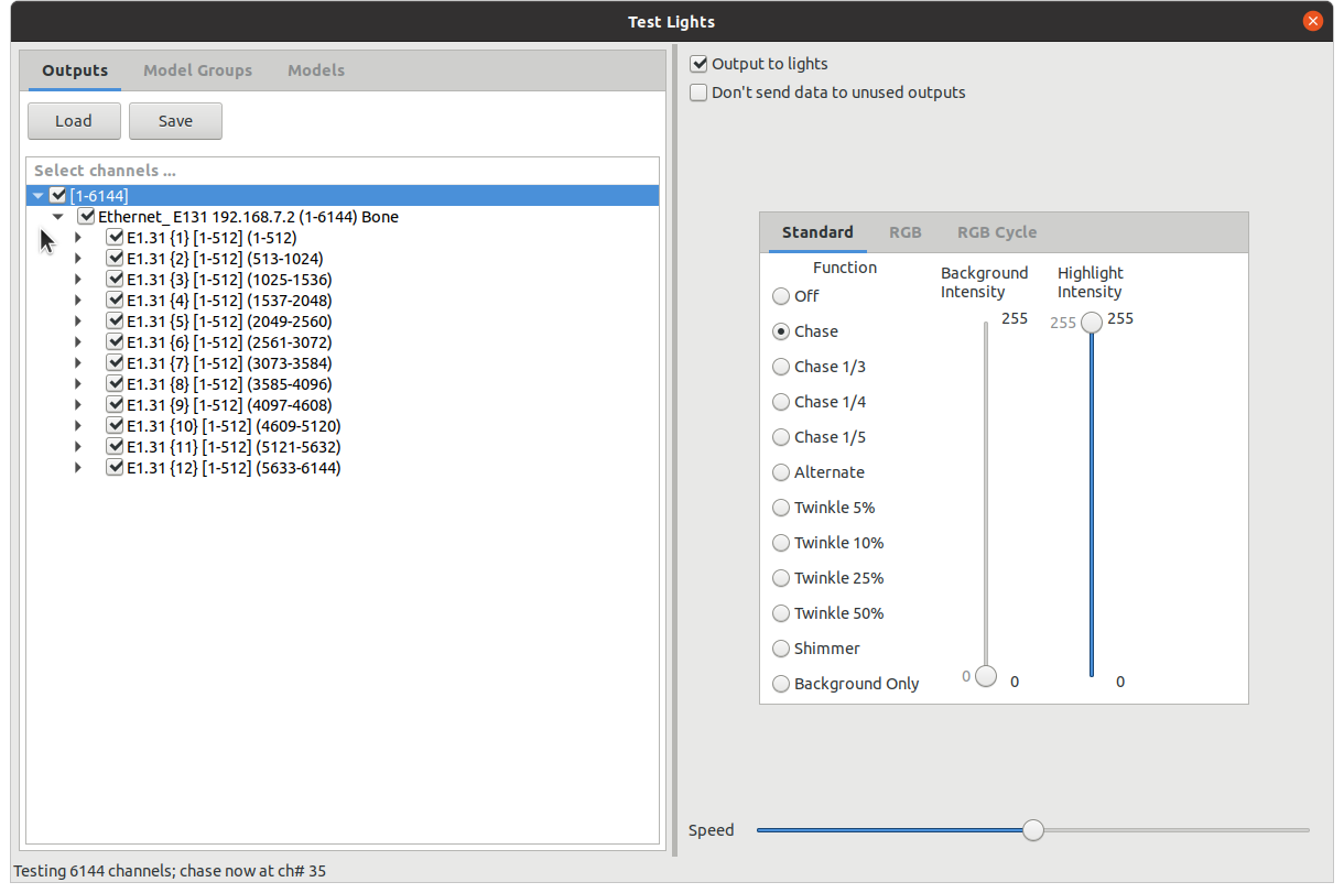
Click the box under Select channels…, click Output to lights and select Twinkle 50%. You matrix should have a colorful twinkle pattern (xLights Twinkle test pattern).
A Simple xLights Sequence
Now that the xLights to FPP link is tested you can generate a sequence to play. Close the Test window and click on the Sequencer tab. Then drag an effect from the Effects box to the timeline that below it. Drop it to the right of the Matrix label (Drag an effect to the timeline). The click Output To Lights which is the yellow lightbulb to the right on the top toolbar. Your matrix should now be displaying your effect.
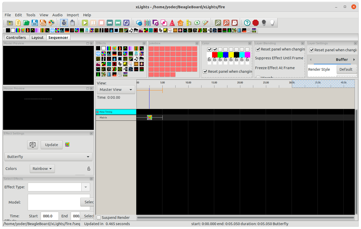
The setup requires the host computer to send the animation data to the Bone. The next section shows how to save the sequence and play it on the Bone standalone.
Saving a Sequence and Playing it Standalone
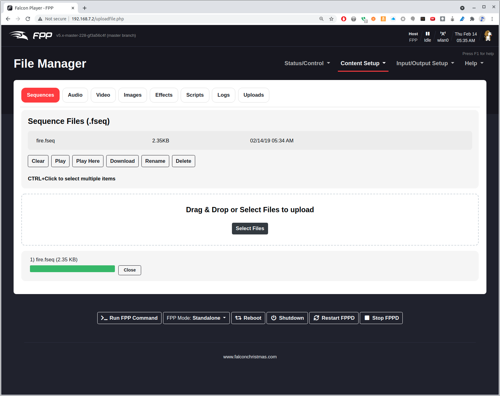
In xLights save your sequence by hitting Ctrl-S and giving it a name. I called mine fire since I used a fire effect. Now, switch back to FPP and select the Content Setup menu and select File Manager. Click the black Select Files button and select your sequence file that ends in .fseq (FPP file manager).
Once your sequence is uploaded, got to Content Steup and select Playlists. Enter you playlist name (I used fire) and click Add. Then click Add a Sequence/Entry and select Sequence Only (Adding a new playlist to FPP), then click Add.
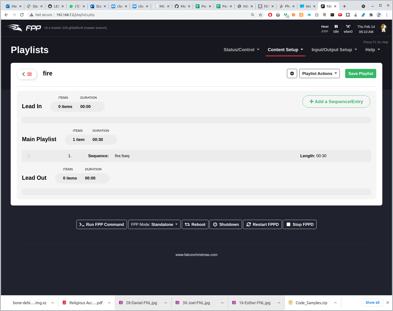
Be sure to click Save Playlist on the right. Now return to Status/Control and Status Page and make sure FPPD Mode: is set to Standalone. You should see your playlist. Click the Play button and your sequence will play.
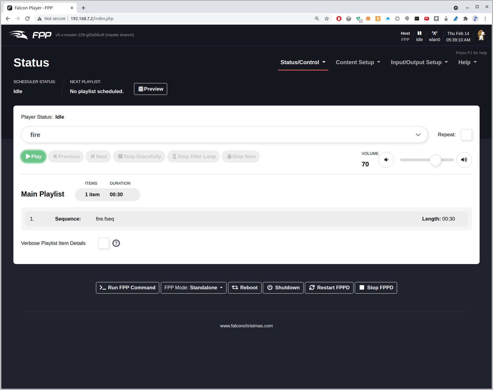
The beauty of the PRU is that the Beagle can play a detailed sequence at 20 frames per second and the ARM procossor is only 15% used. The PRUs are doing all the work.
1.5. simpPRU — A python-like language for programming the PRUs
simpPRU is a simple, python-like programming languge designed to make programming the PRUs easy. It has detailed documentation and many examples.
simpPRU is a procedural programming language that is statically typed.
Variables and functions must be assigned data types during compilation.
It is typesafe, and data types of variables are decided during compilation.
simPRU codes have a .sim extension.
simpPRU provides a console app to use Remoteproc functionality.
You can build simpPRU from source, more easily just install it. On the Beagle run:
  1
2
3
4

  bone$ wget https://github.com/VedantParanjape/simpPRU/releases/download/1.4/simppru-1.4-armhf.deb
bone$ sudo dpkg -i simppru-1.4-armhf.deb
bone$ sudo apt update
bone$ sudo apt install gcc-pru
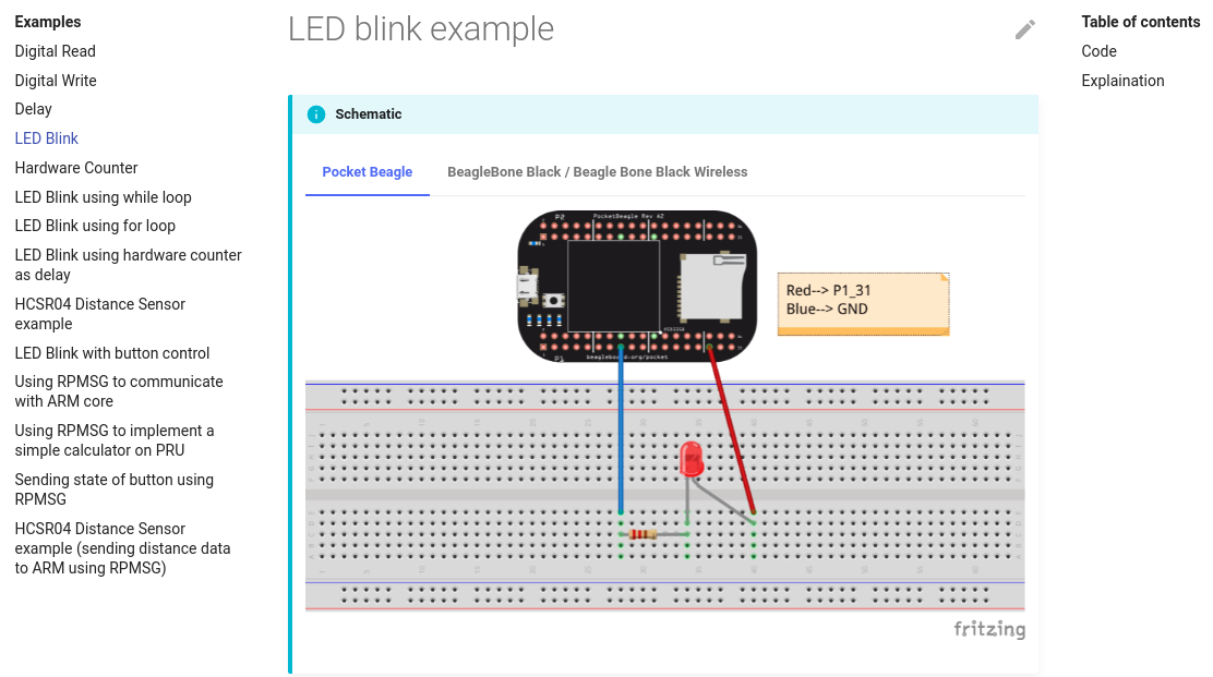
Now, suppose you wanted to run the LED blink example which is reproduced here.
  1
2
3
4
5
6
7

  /* From: https://simppru.readthedocs.io/en/latest/examples/led_blink/ */
while : 1 == 1 {
    digital_write(P1_31, true);
    delay(250);     /* Delay 250 ms */
    digital_write(P1_31, false);
    delay(250);
}
Just run simppru
  1
2
3
4
5
6
7
8

  bone$ simppru blink.sim --load
Detected TI AM335x PocketBeagle
inside while
[4] : setting P1_31 as output

Current mode for P1_31 is:     pruout

Detected TI AM335x PocketBeagle
The --load flag caused the compiled code to be copied to /lib/firmware. To start just do:
  1
2
3
4
5
6

  bone$ cd /dev/remoteproc/pruss-core0/
bone$ ls
device  firmware  name  power  state  subsystem  uevent
bone$ echo start > state
bone$ cat state
running
Your LED should now be blinking.
Check out the many examples (<https://simppru.readthedocs.io/en/latest/examples/led_blink/>).
1.6. MachineKit
MachineKit is a platform for machine control applications. It can control machine tools, robots, or other automated devices. It can control servo motors, stepper motors, relays, and other devices related to machine tools.
Machinekit is portable across a wide range of hardware platforms and real-time environments, and delivers excellent performance at low cost. It is based on the HAL component architecture, an intuitive and easy to use circuit model that includes over 150 building blocks for digital logic, motion, control loops, signal processing, and hardware drivers. Machinekit supports local and networked UI options, including ubiquitous platforms like phones or tablets.
1.7. ArduPilot
ArduPilot is a open source autopilot system supporting multi-copters, traditional helicopters, fixed wing aircraft and rovers. ArduPilot runs on a many hardware platforms including the BeagleBone Black and the BeagleBone Blue.
Ardupilot is the most advanced, full-featured and reliable open source autopilot software available. It has been developed over 5+ years by a team of diverse professional engineers and computer scientists. It is the only autopilot software capable of controlling any vehicle system imaginable, from conventional airplanes, multirotors, and helicopters, to boats and even submarines. And now being expanded to feature support for new emerging vehicle types such as quad-planes and compound helicopters.
Installed in over 1,000,000 vehicles world-wide, and with its advanced data-logging, analysis and simulation tools, Ardupilot is the most tested and proven autopilot software. The open-source code base means that it is rapidly evolving, always at the cutting edge of technology development. With many peripheral suppliers creating interfaces, users benefit from a broad ecosystem of sensors, companion computers and communication systems. Finally, since the source code is open, it can be audited to ensure compliance with security and secrecy requirements.

The software suite is installed in aircraft from many OEM UAV companies, such as 3DR, jDrones, PrecisionHawk, AgEagle and Kespry. It is also used for testing and development by several large institutions and corporations such as NASA, Intel and Insitu/Boeing, as well as countless colleges and universities around the world.