Displays and Other Outputs
Introduction
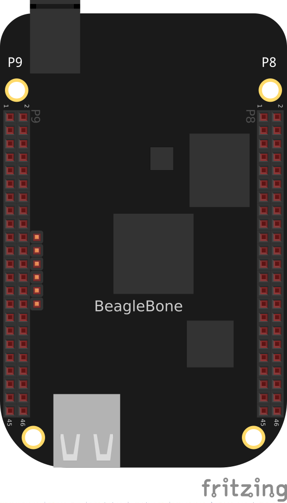
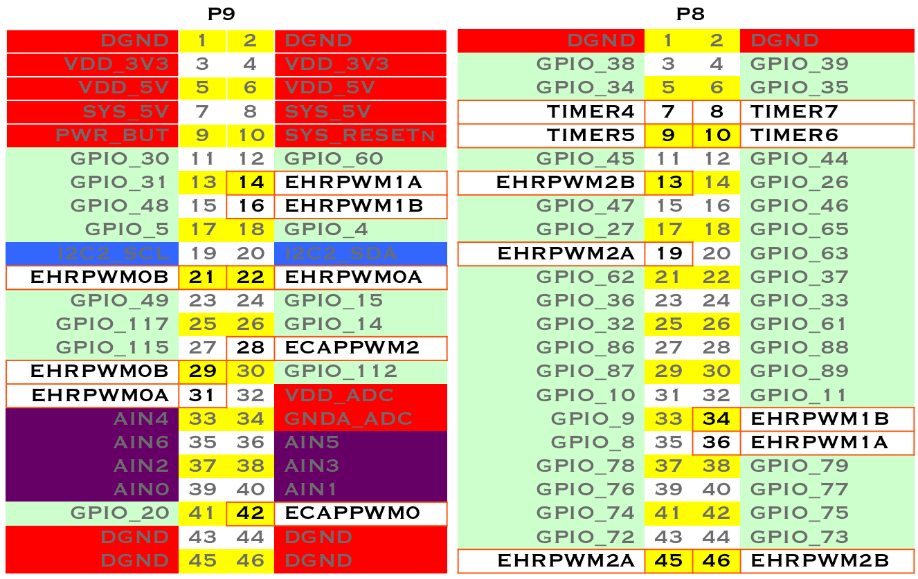
In this chapter, you will learn how to control physical hardware via BeagleBone Black’s general-purpose input/output (GPIO) pins. The Bone has 65 GPIO pins that are brought out on two 46-pin headers, called P8 and P9, as shown in The P8 and P9 GPIO headers.
|
Note
|
All the examples in the book assume you have cloned the Cookbook repository on www.github.com. Go here [basics_repo] for instructions. |
The purpose of this chapter is to give simple examples that show how to use various methods of output. Most solutions require a breadboard and some jumper wires.
All these examples assume that you know how to edit a file ([basics_vsc]) and run it, either within Visual Studio Code (VSC) integrated development environment (IDE) or from the command line ([tips_shell]).
Toggling an Onboard LED
Problem
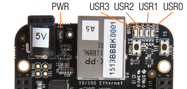
You want to know how to flash the four LEDs that are next to the Ethernet port on the Bone.
Solution
Locate the four onboard LEDs shown in The four USER LEDs. They are labeled USR0 through USR3, but we’ll refer to them as the USER LEDs.
Place the code shown in Using an internal LED (internLED.py) in a file called internLED.py. You can do this using VSC to edit files (as shown in [basics_vsc]) or with a more traditional editor (as shown in [tips_editing_files]).
#!/usr/bin/env python
# //////////////////////////////////////
# 	internalLED.py
# 	Blinks A USR LED.
# 	Wiring:
# 	Setup:
# 	See:
# //////////////////////////////////////
import time

ms = 250      # Blink time in ms
LED = 'usr0'; # LED to blink
LEDPATH = '/sys/class/leds/beaglebone:green:'+LED+'/brightness'

state = '1'    # Initial state

f = open(LEDPATH, "w")

while True:
    f.seek(0)
    f.write(state)
    if (state == '1'):
        state = '0'
    else:
        state = '1'
time.sleep(ms/1000)#!/usr/bin/env node
// //////////////////////////////////////
// internalLED.js
// Blinks the USR LEDs.
// Wiring:
// Setup:
// See:
// //////////////////////////////////////
const fs = require('fs');
const ms = 250; // Blink time in ms
const LED = 'usr0'; // LED to blink
const LEDPATH = '/sys/class/leds/beaglebone:green:'+LED+'/brightness';
var state = '1'; // Initial state
setInterval(flash, ms); // Change state every ms
function flash() {
fs.writeFileSync(LEDPATH, state)
if(state === '1') {
state = '0';
} else {
state = '1';
}
}In the bash command window, enter the following commands:
bone$ cd ~/BoneCookbook/docs/03displays/code
bone$ ./internLED.js
The USER0 LED should now be flashing.
Toggling an External LED
Problem
You want to connect your own external LED to the Bone.
Solution
Connect an LED to one of the GPIO pins using a series resistor to limit the current. To make this recipe, you will need:
-
Breadboard and jumper wires
-
220 Ω to 470 Ω resistor
-
LED
|
Warning
|
The value of the current limiting resistor depends on the LED you are using. The Bone can drive only 4 to 6 mA, so you might need a larger resistor to keep from pulling too much current. A 330 Ω or 470 Ω resistor might be better. |
Diagram for using an external LED shows how you can wire the LED to pin 14 of the P9 header (P9_14). Every circuit in this book ([basics_wire_breadboard]) assumes you have already wired the rightmost bus to ground (P9_1) and the next bus to the left to the 3.3 V (P9_3) pins on the header. Be sure to get the polarity right on the LED. The short lead always goes to ground.
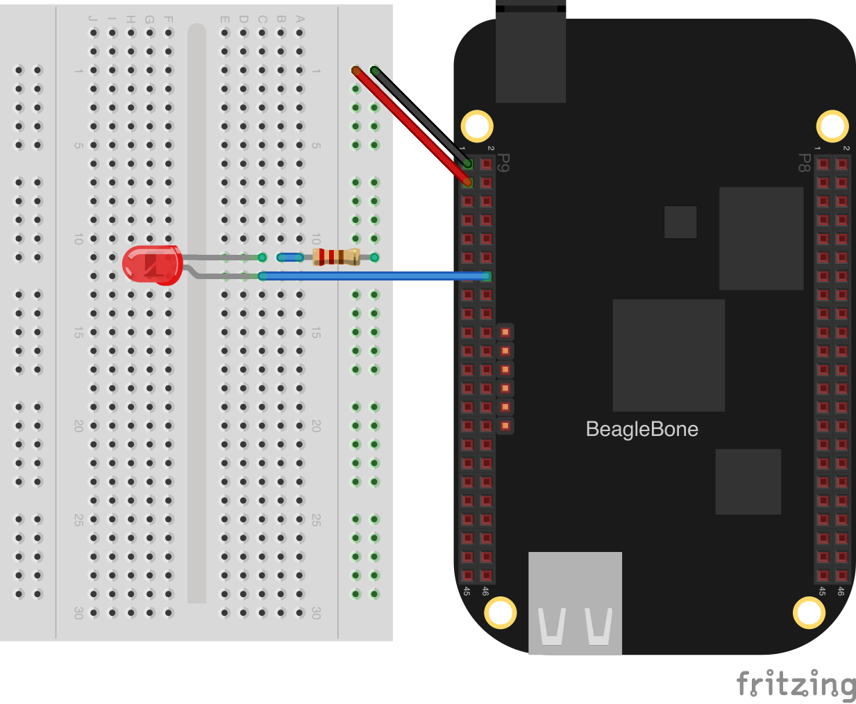
After you’ve wired it, start VSC (see [basics_vsc]) and find the code shown in Code for using an external LED (externLED.py).
#!/usr/bin/env python
# ////////////////////////////////////////
# //	externalLED.py
# //	Blinks an external LED wired to P9_14.
# //	Wiring: P9_14 connects to the plus lead of an LED.  The negative lead of the
#			LED goes to a 220 Ohm resistor.  The other lead of the resistor goes
#			to ground.
# //	Setup:
# //	See:
# ////////////////////////////////////////
import time
import os

ms = 250        # Time to blink in ms
# Look up P9.14 using gpioinfo | grep -e chip -e P9.14.  chip 1, line 18 maps to 50
pin = '50'

GPIOPATH='/sys/class/gpio/'
# Make sure pin is exported
if (not os.path.exists(GPIOPATH+"gpio"+pin)):
    f = open(GPIOPATH+"export", "w")
    f.write(pin)
    f.close()

# Make it an output pin
f = open(GPIOPATH+"gpio"+pin+"/direction", "w")
f.write("out")
f.close()

f = open(GPIOPATH+"gpio"+pin+"/value", "w")
# Blink
while True:
    f.seek(0)
    f.write("1")
    time.sleep(ms/1000)

    f.seek(0)
    f.write("0")
    time.sleep(ms/1000)
f.close()#!/usr/bin/env node
////////////////////////////////////////
// externalLED.js
// Blinks the P9_14 pin
// Wiring:
// Setup:
// See:
////////////////////////////////////////
const fs = require("fs");
// Look up P9.14 using gpioinfo | grep -e chip -e P9.14. chip 1, line 18 maps to 50
pin="50";
GPIOPATH="/sys/class/gpio/";
// Make sure pin is exported
if(!fs.existsSync(GPIOPATH+"gpio"+pin)) {
fs.writeFileSync(GPIOPATH+"export", pin);
}
// Make it an output pin
fs.writeFileSync(GPIOPATH+"gpio"+pin+"/direction", "out");
// Blink every 500ms
setInterval(toggle, 500);
state="1";
function toggle() {
fs.writeFileSync(GPIOPATH+"gpio"+pin+"/value", state);
if(state == "0") {
state = "1";
} else {
state = "0";
}
}Save your file and run the code as before (Toggling an Onboard LED).
Discussion
This method of controlling and external device uses sysfs, a virtual file system that exposes drivers to userspace. /sys/class is a comment interace.
bone$ cd /sys/class
bone$ ls
ata_device  devcoredump     extcon           hidraw       leds      phy           rtc          tpm        usb_role
ata_link    devfreq         firmware         hwmon        mbox      power_supply  scsi_device  tpmrm      vc
ata_port    devfreq-event   gb_authenticate  i2c-adapter  mdio_bus  pps           scsi_disk    tty        video4linux
backlight   devlink         gb_fw_mgmt       i2c-dev      mem       ptp           scsi_host    typec      vtconsole
bdi         dma             gb_loopback      ieee802154   misc      pwm           spi_master   typec_mux  wakeup
block       drm             gb_raw           input        mmc_host  regulator     spi_slave    ubi        watchdog
bluetooth   drm_dp_aux_dev  gpio             iommu        mtd       remoteproc    spidev       udc
bsg         dvb             graphics         lcd          net       rfkill        thermal      uio
There are many interfaces. We’re interested in the gpio interface.
bone$ cd gpio
bone$ ls
export   gpio113  gpio13  gpio23  gpio32  gpio38  gpio47  gpio60  gpio67  gpio72  gpio78  gpio87      gpiochip64
gpio10   gpio114  gpio14  gpio26  gpio33  gpio39  gpio48  gpio61  gpio68  gpio73  gpio79  gpio88      gpiochip96
gpio11   gpio115  gpio15  gpio27  gpio34  gpio4   gpio49  gpio62  gpio69  gpio74  gpio8   gpio89      unexport
gpio110  gpio116  gpio2   gpio3   gpio35  gpio44  gpio5   gpio63  gpio7   gpio75  gpio80  gpio9
gpio111  gpio117  gpio20  gpio30  gpio36  gpio45  gpio50  gpio65  gpio70  gpio76  gpio81  gpiochip0
gpio112  gpio12   gpio22  gpio31  gpio37  gpio46  gpio51  gpio66  gpio71  gpio77  gpio86  gpiochip32
In the code in Toggling an External LED we saw P9_14 is pin 50. That same 50 maps to the gpio50 directory shown above. If gpio50 doesn’t show up, export it. A close ook at the Python and JavaScript code shows it looks for gpio50 and exports it if it isn’t there.
bone$ echo 50 > export
bone$ cd gpio50
bone$ ls
active_low  device  direction  edge  label  power  subsystem  uevent  value
bone$ cat direction
out
bone$ cat value
1
Here we see it’s configured to be an output and it’s currently turned on. Turn it off with:
bone$ echo 0 > value
The LED should now be off.
Toggling an External LED via gpiod
Problem
You hear sysfs is dead and want to know what to use instead.
Solution
sysfs is deprecated, but most believe it will be around for a long time. The repository has many examples of gpiod in docs/03displays/code/gpiod. Here’s an example:
#!/usr/bin/env python3
# //////////////////////////////////////
# 	toggle1.py
#  Toggles the P9_14 pin as fast as it can. P9_14 is line 18 on chip 1.
# 	Wiring:	Attach an oscilloscope to P9_14 to see the squarewave or
#          uncomment the sleep and attach an LED.
# 	Setup:	sudo apt update; pip install gpiod
# 	See:	https://git.kernel.org/pub/scm/libs/libgpiod/libgpiod.git/tree/bindings/python/examples
# //////////////////////////////////////

import gpiod
import time

LED_CHIP = 'gpiochip1'
LED_LINE_OFFSET = [18]  # P9_14

chip = gpiod.Chip(LED_CHIP)

lines = chip.get_lines(LED_LINE_OFFSET)
lines.request(consumer='blink', type=gpiod.LINE_REQ_DIR_OUT)

while True:
    lines.set_values([0])
    time.sleep(0.1)
    lines.set_values([1])
    time.sleep(0.1)
Toggling a High-Voltage External Device
Problem
You want to control a device that runs at 120 V.
Solution
Working with 120 V can be tricky—even dangerous—if you aren’t careful. Here’s a safe way to do it.
To make this recipe, you will need:
-
PowerSwitch Tail II
Diagram for wiring PowerSwitch Tail II shows how you can wire the PowerSwitch Tail II to pin P9_14.
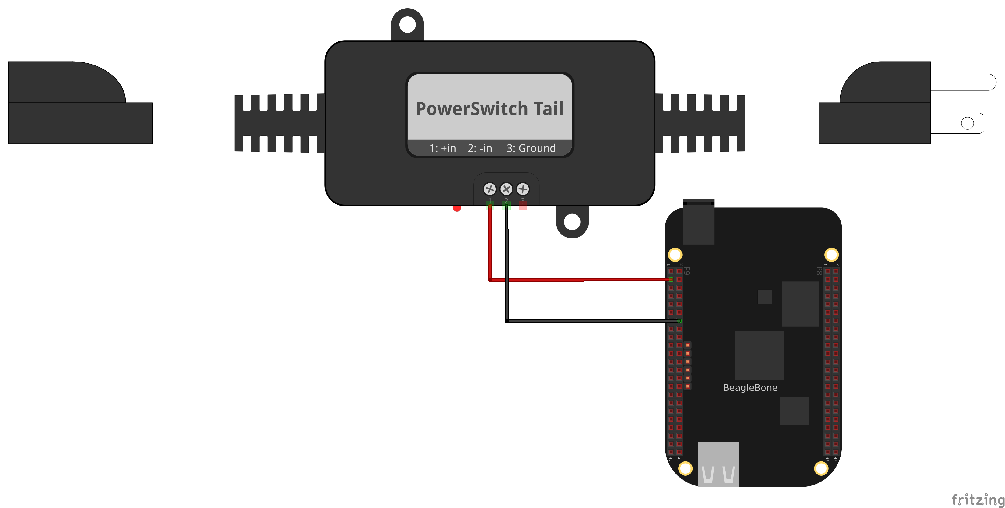
After you’ve wired it, because this uses the same output pin as Toggling an External LED, you can run the same code (Code for using an external LED (externLED.py)).
Fading an External LED
Problem
You want to change the brightness of an LED from the Bone.
Solution
Use the Bone's pulse width modulation (PWM) hardware to fade an LED. We'll use the same circuit as before (<<displays_externLED_fig>>). Find the code in <<py_fadeLED_code>> Next configure the pins. We are using P9_14 so run:
bone$ config-pin P9_14 pwm
Then run it as before.
#!/usr/bin/env python
# ////////////////////////////////////////
# //	fadeLED.py
# //	Blinks the P9_14 pin
# //	Wiring:
# //	Setup:  config-pin P9_14 pwm
# //	See:
# ////////////////////////////////////////
import time
ms = 20;   # Fade time in ms

pwmPeriod = 1000000    # Period in ns
pwm     = '1'  # pwm to use
channel = 'a'  # channel to use
PWMPATH='/dev/bone/pwm/'+pwm+'/'+channel
step = 0.02    # Step size
min = 0.02     # dimmest value
max = 1        # brightest value
brightness = min # Current brightness

f = open(PWMPATH+'/period', 'w')
f.write(str(pwmPeriod))
f.close()

f = open(PWMPATH+'/enable', 'w')
f.write('1')
f.close()

f = open(PWMPATH+'/duty_cycle', 'w')
while True:
    f.seek(0)
    f.write(str(round(pwmPeriod*brightness)))
    brightness  += step
    if(brightness >= max or brightness <= min):
        step = -1 * step
    time.sleep(ms/1000)

# | Pin   | pwm | channel
# | P9_31 | 0   | a
# | P9_29 | 0   | b
# | P9_14 | 1   | a
# | P9_16 | 1   | b
# | P8_19 | 2   | a
# | P8_13 | 2 | b#!/usr/bin/env node
////////////////////////////////////////
// fadeLED.js
// Blinks the P9_14 pin
// Wiring:
// Setup: config-pin P9_14 pwm
// See:
////////////////////////////////////////
const fs = require("fs");
const ms = '20'; // Fade time in ms
const pwmPeriod = '1000000'; // Period in ns
const pwm = '1'; // pwm to use
const channel = 'a'; // channel to use
const PWMPATH='/dev/bone/pwm/'+pwm+'/'+channel;
var step = 0.02; // Step size
const min = 0.02, // dimmest value
max = 1; // brightest value
var brightness = min; // Current brightness;
// Set the period in ns
fs.writeFileSync(PWMPATH+'/period', pwmPeriod);
fs.writeFileSync(PWMPATH+'/duty_cycle', pwmPeriod/2);
fs.writeFileSync(PWMPATH+'/enable', '1');
setInterval(fade, ms); // Step every ms
function fade() {
fs.writeFileSync(PWMPATH+'/duty_cycle',
parseInt(pwmPeriod*brightness));
brightness += step;
if(brightness >= max || brightness <= min) {
step = -1 * step;
}
}
// | Pin | pwm | channel
// | P9_31 | 0 | a
// | P9_29 | 0 | b
// | P9_14 | 1 | a
// | P9_16 | 1 | b
// | P8_19 | 2 | a
// | P8_13 | 2 | bDiscussion
The Bone has several outputs that can be used as pwm’s as shown in Table of PWM outputs. There are three EHRPWM's (enhanced high resolution pulse width modulation) which each has a pair of pwm channels. Each pair must have the same pulse period.
The pwm’s are accessed through /dev/bone/pwm
bone$ cd /dev/bone/pwm
bone$ ls
0  1  2
Here we see three pwmchips that can be used, each has two channels. Explore one.
bone$ cd 1
bone$ ls
a  b
bone$ cd a
bone$ ls
capture  duty_cycle  enable  period  polarity  power  uevent
Here is where you can set the period and duty_cycle (in ns) and enable the pwm. Attach in LED to P9_14 and if you set the period long enough you can see the LED flash.
bone$ echo 1000000000 > period
bone$ echo  500000000 > duty_cycle
bone$ echo 1 > enable
Your LED should now be flashing.
Headers to pwm channel mapping. are the mapping I’ve figured out so far. I don’t know how to get to the timers.
Pin |
pwm |
channel |
P9_31 |
0 |
a |
P9_29 |
0 |
b |
P9_14 |
1 |
a |
P9_16 |
1 |
b |
P8_19 |
2 |
a |
P8_13 |
2 |
b |
Writing to an LED Matrix
Problem
You have an I2C-based LED matrix to interface.
Solution
There are a number of nice LED matrices that allow you to control several LEDs via one interface. This solution uses an Adafruit Bicolor 8x8 LED Square Pixel Matrix w/I2C Backpack.
To make this recipe, you will need:
-
Breadboard and jumper wires
-
Two 4.7 kΩ resistors
-
I2C LED matrix
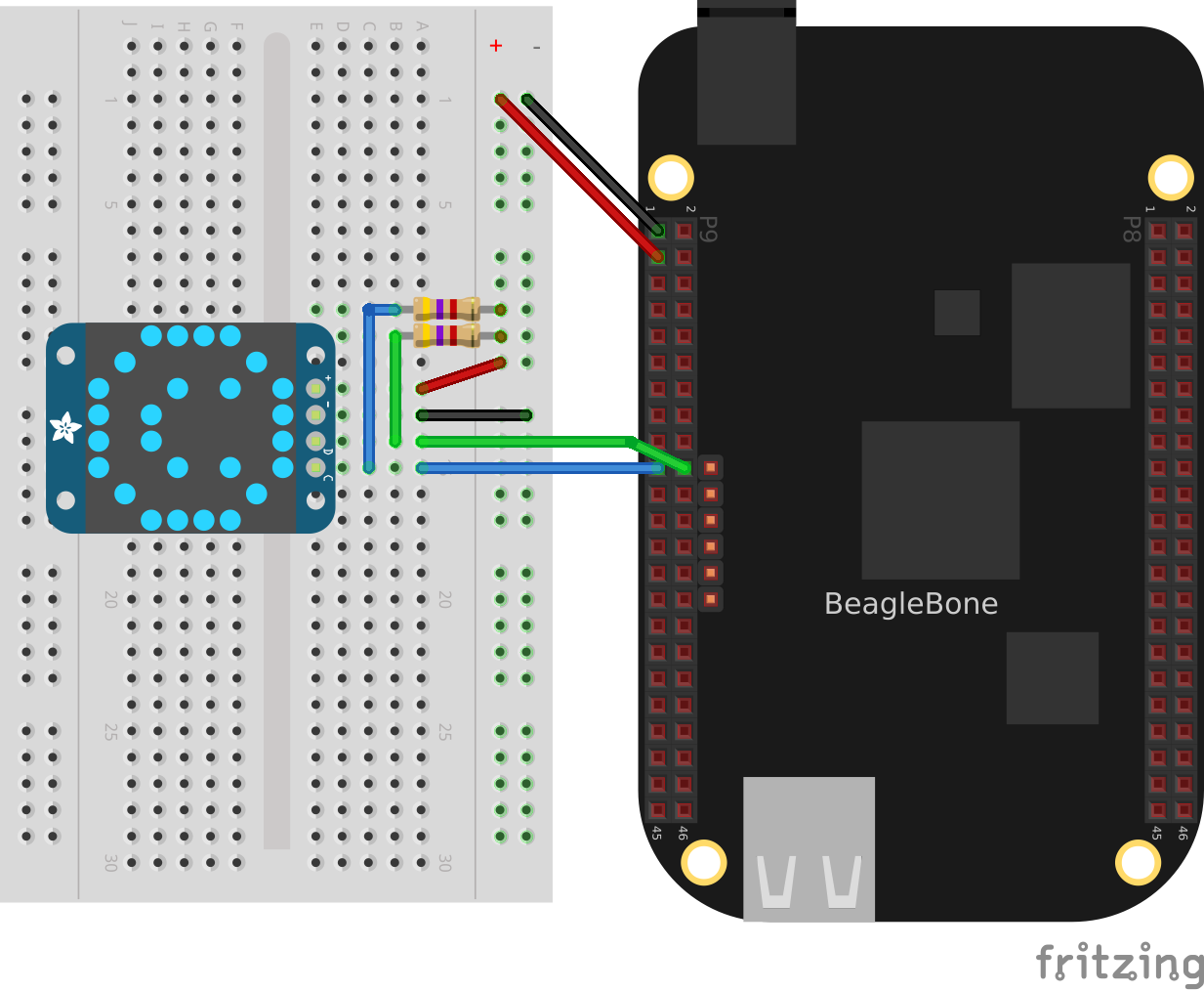
The LED matrix is a 5 V device, but you can drive it from 3.3 V. Wire, as shown in Wiring an I2C LED matrix.
[sensors_i2c_temp] shows how to use i2cdetect to discover the address of an I2C device.
Run the i2cdetect -y -r 2 command to discover the address of the display on I2C bus 2, as shown in Using I2C command-line tools to discover the address of the display.
bone$ i2cdetect -y -r 2
     0  1  2  3  4  5  6  7  8  9  a  b  c  d  e  f
00:          -- -- -- -- -- -- -- -- -- -- -- -- --
10: -- -- -- -- -- -- -- -- -- -- -- -- -- -- -- --
20: -- -- -- -- -- -- -- -- -- -- -- -- -- -- -- --
30: -- -- -- -- -- -- -- -- -- -- -- -- -- -- -- --
40: -- -- -- -- -- -- -- -- -- 49 -- -- -- -- -- --
50: -- -- -- -- UU UU UU UU -- -- -- -- -- -- -- --
60: -- -- -- -- -- -- -- -- -- -- -- -- -- -- -- --
70: 70 -- -- -- -- -- -- --
Here, you can see a device at 0x49 and 0x70. I know I have a temperature sensor at 0x49, so the LED matrix must be at 0.70.
Find the code in LED matrix display (matrixLEDi2c.py) and run it by using the following command:
bone$ pip install smbus  # (Do this only once.)
bone$ ./matrixLEDi2c.py
#!/usr/bin/env python
# ////////////////////////////////////////
# //	i2cTemp.py
# //      Write an 8x8 Red/Green LED matrix.
# //	Wiring:	Attach to i2c as shown in text.
# //	Setup:	echo tmp101 0x49 > /sys/class/i2c-adapter/i2c-2/new_device
# //	See:	https://www.adafruit.com/product/902
# ////////////////////////////////////////
import smbus
import time

bus = smbus.SMBus(2)  # Use i2c bus 2       (1)
matrix = 0x70         # Use address 0x70    (2)
ms = 1;               # Delay between images in ms

# The first byte is GREEN, the second is RED.   (3)
smile = [0x00, 0x3c, 0x00, 0x42, 0x28, 0x89, 0x04, 0x85,
    0x04, 0x85, 0x28, 0x89, 0x00, 0x42, 0x00, 0x3c
]
frown = [0x3c, 0x00, 0x42, 0x00, 0x85, 0x20, 0x89, 0x00,
    0x89, 0x00, 0x85, 0x20, 0x42, 0x00, 0x3c, 0x00
]
neutral = [0x3c, 0x3c, 0x42, 0x42, 0xa9, 0xa9, 0x89, 0x89,
    0x89, 0x89, 0xa9, 0xa9, 0x42, 0x42, 0x3c, 0x3c
]

bus.write_byte_data(matrix, 0x21, 0)   # Start oscillator (p10) (4)
bus.write_byte_data(matrix, 0x81, 0)   # Disp on, blink off (p11)
bus.write_byte_data(matrix, 0xe7, 0)   # Full brightness (page 15)

bus.write_i2c_block_data(matrix, 0, frown)      # (5)
for fade in range(0xef, 0xe0, -1):              # (6)
    bus.write_byte_data(matrix, fade, 0)
    time.sleep(ms/10)

bus.write_i2c_block_data(matrix, 0, neutral)
for fade in range(0xe0, 0xef, 1):
    bus.write_byte_data(matrix, fade, 0)
    time.sleep(ms/10)

bus.write_i2c_block_data(matrix, 0, smile)-
This line states which bus to use.
-
This specifies the address of the LED matrix, 0x70 in our case.
-
This indicates which LEDs to turn on. The first byte is for the first column of green LEDs. In this case, all are turned off. The next byte is for the first column of red LEDs. The hex 0x3c number is 0b00111100 in binary. This means the first two red LEDs are off, the next four are on, and the last two are off. The next byte (0x00) says the second column of green LEDs are all off, the fourth byte (0x42 = 0b01000010) says just two red LEDs are on, and so on. Declarations define four different patterns to display on the LED matrix, the last being all turned off.
-
Send three commands to the matrix to get it ready to display.
-
Now, we are ready to display the various patterns. After each pattern is displayed, we sleep a certain amount of time so that the pattern can be seen.
-
Finally, send commands to the LED matrix to set the brightness. This makes the disply fade out and back in again.
Driving a 5 V Device
Problem
You have a 5 V device to drive, and the Bone has 3.3 V outputs.
Solution
If you are lucky, you might be able to drive a 5 V device from the Bone’s 3.3 V output. Try it and see if it works. If not, you need a level translator.
What you will need for this recipe:
-
A PCA9306 level translator
-
A 5 V power supply (if the Bone’s 5 V power supply isn’t enough)
The PCA9306 translates signals at 3.3 V to 5 V in both directions. It’s meant to work with I2C devices that have a pull-up resistor, but it can work with anything needing translation.
Wiring a PCA9306 level translator to an LED matrix shows how to wire a PCA9306 to an LED matrix. The left is the 3.3 V side and the right is the 5 V side. Notice that we are using the Bone’s built-in 5 V power supply.
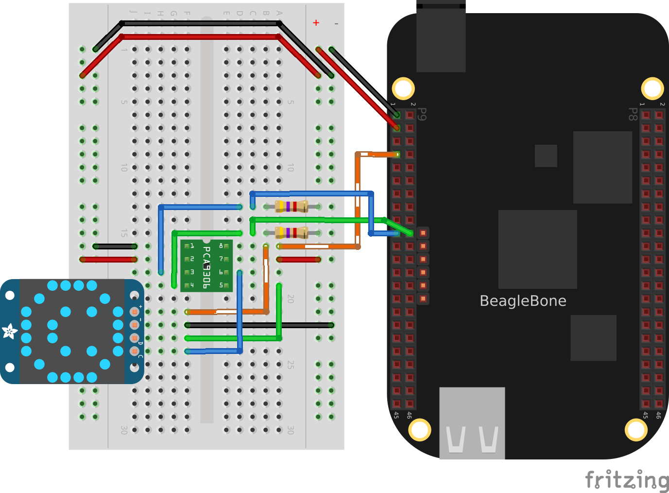
|
Note
|
If your device needs more current than the Bone’s 5 V power supply provides, you can wire in an external power supply. |
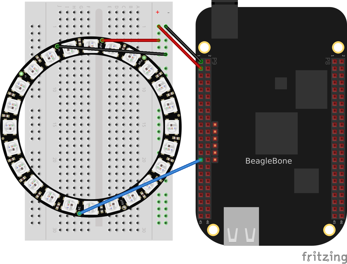
Writing to a NeoPixel LED String Using the PRUs
Problem
You have an Adafruit NeoPixel LED string or Adafruit NeoPixel LED matrix and want to light it up.
Solution
The PRU Cookbook has a nice discussion (WS2812 (NeoPixel) driver) on driving NeoPixels.