1. More Performance
So far in all our examples we’ve been able to meet our timing goals by writing our code in the C programming language. The C compiler does a suprisingly good job at generating code, most the time. However there are times when very precise timing is needed and the compiler isn’t doing it.
At these times you need to write in assembly language. This chapter introduces the PRU assembler and shows how to call assembly code from C. Detailing on how to program in assembly are beyond the scope of this text.
The following are resources used in this chapter.
1.1. Calling Assembly from C
Problem
You have some C code and you want to call an assembly language routine from it.
Solution
You need to do two things, write the assembler file and modify the Makefile
to include it. For example, let’s write our own my_delay_cycles routine in
in assembly. The intrinsic __delay_cycles must be passed a compile time
constant. Our new delay_cycles can take a runtime delay value.
delay-test.pru0.c is much like our other c code, but on line 10 we declare
my_delay_cycles and then on lines 24 and 26 we’ll call it with an argument
of 1.
  1
2
3
4
5
6
7
8
9
10
11
12
13
14
15
16
17
18
19
20
21
22
23
24
25
26
27
28

  // Shows how to call an assembly routine with one parameter
#include <stdint.h>
#include <pru_cfg.h>
#include "resource_table_empty.h"
#include "prugpio.h"

// The function is defined in delay.asm in same dir
// We just need to add a declaration here, the defination can be
// seperately linked
extern void my_delay_cycles(uint32_t);

volatile register uint32_t R30;
volatile register uint32_t R31;

void main(void)
{
    uint32_t gpio = P9_31;  // Select which pin to toggle.;

    /* Clear SYSCFG[STANDBY_INIT] to enable OCP master port */
    CT_CFG.SYSCFG_bit.STANDBY_INIT = 0;

    while(1) {
        R30 |= gpio;      // Set the GPIO pin to 1
        my_delay_cycles(1);
        R30 &= ~gpio;     // Clear the GPIO pin
        my_delay_cycles(1);
    }
}
delay.pru0.asm is the assembly code.
  1
2
3
4
5
6
7
8
9

  ; This is an example of how to call an assembly routine from C.
;   Mark A. Yoder, 9-July-2018
    .global my_delay_cycles
my_delay_cycles:
delay:
    sub     r14,   r14, 1       ; The first argument is passed in r14
    qbne    delay, r14, 0

    jmp     r3.w2           ; r3 contains the return address
The Makefile has one addition that needs to be made to compile both delay-test.pru0.c
and delay.pru0.asm.
If you look in the local Makefile you’ll see:
include /var/lib/cloud9/common/MakefileThis Makefle includes a common Makfile at /var/lib/cloud9/common/Makefile,
this the Makefile you need to edit.
Edit /var/lib/cloud9/common/Makefile and go to line 195.
$(GEN_DIR)/%.out: $(GEN_DIR)/%.o $(GEN_DIR)/$(TARGETasm).o
    @mkdir -p $(GEN_DIR)
    @echo 'LD   $^'
    $(eval $(call target-to-proc,$@))
    $(eval $(call proc-to-build-vars,$@))
    @$(LD) $@ $^ $(LDFLAGS)
Add (GEN_DIR)/$(TARGETasm).o as shown in bold above. You will want to remove
this addition once you are done with this example since it will break the other examples.
The following will compile and run everything.
bone$ config-pin P9_31 pruout
bone$ make TARGET=delay-test.pru0 TARGETasm=delay.pru0
/var/lib/cloud9/common/Makefile:29: MODEL=TI_AM335x_BeagleBone_Black,TARGET=delay-test.pru0
-    Stopping PRU 0
-   copying firmware file /tmp/cloud9-examples/delay-test.pru0.out to /lib/firmware/am335x-pru0-fw
write_init_pins.sh
-    Starting PRU 0
MODEL   = TI_AM335x_BeagleBone_Black
PROC    = pru
PRUN    = 0
PRU_DIR = /sys/class/remoteproc/remoteproc1
The resulting output is shown in Output of my_delay_cycles().
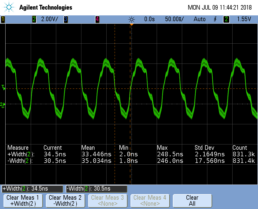
Notice the on time is about 35ns and the off time is 30ns.
Discission
There is much to explain here. Let’s start with delay.pru0.asm.
| Line | Explanation |
|---|---|
3 |
Declare |
4 |
Label the starting point for |
5 |
Label for our delay loop. |
6 |
The first argument is passed in register Here we subtract 1 from |
7 |
|
9 |
Once we’ve delayed enough we drop through the quick branch and
hit the jump. The upper bits of register |
Output of my_delay_cycles() shows the on time is 35ns and the off time is 30ns.
With 5ns/cycle this gives 7 cycles on and 6 off. These times make sense
because each instruction takes a cycle and you have, set R30, jump to
my_delay_cycles, sub, qbne, jmp. Plus the instruction (not seen) that
initilizes r14 to the passed value. That’s a total of six instructions.
The extra instruction is the branch at the bottom of the while loop.
1.2. Returning a Value from Assembly
Problem
Your assembly code needs to return a value.
Solution
R14 is how the return value is passed back. delay-test2.pru0.c shows the c
code.
  1
2
3
4
5
6
7
8
9
10
11
12
13
14
15
16
17
18
19
20
21
22
23
24
25
26
27
28
29
30
31
32

  // Shows how to call an assembly routine with a return value
#include <stdint.h>
#include <pru_cfg.h>
#include "resource_table_empty.h"
#include "prugpio.h"

#define TEST    100

// The function is defined in delay.asm in same dir
// We just need to add a declaration here, the defination can be
// seperately linked
extern uint32_t my_delay_cycles(uint32_t);

uint32_t ret;

volatile register uint32_t R30;
volatile register uint32_t R31;

void main(void)
{
    uint32_t gpio = P9_31;  // Select which pin to toggle.;

    /* Clear SYSCFG[STANDBY_INIT] to enable OCP master port */
    CT_CFG.SYSCFG_bit.STANDBY_INIT = 0;

    while(1) {
        R30 |= gpio;      // Set the GPIO pin to 1
        ret = my_delay_cycles(1);
        R30 &= ~gpio;     // Clear the GPIO pin
        ret = my_delay_cycles(1);
    }
}
delay2.pru0.asm is the assembly code.
  1
2
3
4
5
6
7
8
9
10
11
12
13
14
15

  ; This is an example of how to call an assembly routine from C with a retun value.
;   Mark A. Yoder, 9-July-2018

    .cdecls "delay-test2.pru0.c"

    .global my_delay_cycles
my_delay_cycles:
delay:
    sub     r14,   r14, 1       ; The first argument is passed in r14
    qbne    delay, r14, 0

    ldi     r14, TEST       ; TEST is defined in delay-test2.c
                            ; r14 is the return register

    jmp     r3.w2           ; r3 contains the return address
An additional feature is shown in line 4 of delay2.pru0.asm. The
.cdecls "delay-test2.pru0.c" says to include any defines from delay-test2.pru0.c
In this example, line 6 of delay-test2.pru0.c #defines TEST and line 12 of
delay2.pru0.asm reference it.
1.3. Using the Built-In Counter for Timing
Problem
I want to count how many cycles my routine takes.
Solution
Each PRU has a CYCLE register which counts the number of cycles since
the PRU was enabled. They also have a STALL register that counts how
many times the PRU stalled fetching an instruction.
cycle.pru0.c - Code to count cycles. shows they are used.
  1
2
3
4
5
6
7
8
9
10
11
12
13
14
15
16
17
18
19
20
21
22
23
24
25
26
27
28
29
30
31
32

  // Access the CYCLE and STALL registers
#include <stdint.h>
#include <pru_cfg.h>
#include <pru_ctrl.h>
#include "resource_table_empty.h"
#include "prugpio.h"

volatile register uint32_t R30;
volatile register uint32_t R31;

void main(void)
{
    uint32_t gpio = P9_31;  // Select which pin to toggle.;

    // These will be kept in registers and never witten to DRAM
    uint32_t cycle, stall;

    // Clear SYSCFG[STANDBY_INIT] to enable OCP master port
    CT_CFG.SYSCFG_bit.STANDBY_INIT = 0;

    PRU0_CTRL.CTRL_bit.CTR_EN = 1;  // Enable cycle counter

    R30 |= gpio;              // Set the GPIO pin to 1
    // Reset cycle counter, cycle is on the right side to force the compiler
    // to put it in it's own register
    PRU0_CTRL.CYCLE = cycle;
    R30 &= ~gpio;             // Clear the GPIO pin
    cycle = PRU0_CTRL.CYCLE;    // Read cycle and store in a register
    stall = PRU0_CTRL.STALL;    // Ditto for stall

    __halt();
}
Discission
The code is mostly the same as other examples.
cycle and stall end up in registers which
we can read using prudebug.
Line-by-line for cycle.pru0.c is the Line-by-line.
| Line | Explanation |
|---|---|
4 |
Include needed to reference |
16 |
Declaring |
21 |
Enables |
26 |
Reset |
28, 29 |
Reads the |
You can see where cycle and stall are stored by looking into
/tmp/cloud9-examples/cycle.pru0.lst Lines 113..119.
  1
2
3
4
5
6
7

       103;----------------------------------------------------------------------
     104;  23 | PRU0_CTRL.CTRL_bit.CTR_EN = 1;  // Enable cycle counter
     105;----------------------------------------------------------------------
     106 0000000c 200080240002C0          LDI32     r0, 0x00022000        ; [ALU_PRU] |23| $O$C1
     107 00000014 000000F1002081          LBBO      &r1, r0, 0, 4         ; [ALU_PRU] |23|
     108 00000018 0000001F03E1E1          SET       r1, r1, 0x00000003    ; [ALU_PRU] |23|
     109 0000001c 000000E1002081          SBBO      &r1, r0, 0, 4         ; [ALU_PRU] |23|
Here the LDI32 instruction loads the address 0x22000 into r0.
This is the offset to the CTRL registers.
Later in the file we see /tmp/cloud9-examples/cycle.pru0.lst Lines 146..152.
  1
2
3
4
5
6
7

       131;----------------------------------------------------------------------
     132 0000002c 000000F10C2081          LBBO      &r1, r0, 12, 4        ; [ALU_PRU] |30| $O$C1
     133        .dwpsn  file "cycle.pru0.c",line 31,column 2,is_stmt,isa 0
     134;----------------------------------------------------------------------
     135;  31 | stall = PRU0_CTRL.STALL;        // Ditto for stall
     136;----------------------------------------------------------------------
     137 00000030 000000F1102080          LBBO      &r0, r0, 16, 4        ; [ALU_PRU] |31| $O$C1
The first LBBO takes the contents of r0 and adds the offset 12 to it and
copies 4 bytes into r1. This points to CYCLE, so r1 has the contents of
CYCLE.
The second LBBO does the same, but with offset 16, which points to STALL,
thus STALL is now in r0.
Now fire up prudebug and look at those registers.
bone$ sudo prudebug
PRU0> r
r
r
Register info for PRU0
    Control register: 0x00000009
      Reset PC:0x0000  STOPPED, FREE_RUN, COUNTER_ENABLED, NOT_SLEEPING, PROC_DISABLED

    Program counter: 0x0012
      Current instruction: HALT

    R00: 0x00000005    R08: 0x00000200    R16: 0x000003c6    R24: 0x00110210
    R01: 0x00000003    R09: 0x00000000    R17: 0x00000000    R25: 0x00000000
    R02: 0x000000fc    R10: 0xfff4ea57    R18: 0x000003e6    R26: 0x6e616843
    R03: 0x0004272c    R11: 0x5fac6373    R19: 0x30203020    R27: 0x206c656e
    R04: 0xffffffff    R12: 0x59bfeafc    R20: 0x0000000a    R28: 0x00003033
    R05: 0x00000007    R13: 0xa4c19eaf    R21: 0x00757270    R29: 0x02100000
    R06: 0xefd30a00    R14: 0x00000005    R22: 0x0000001e    R30: 0xa03f9990
    R07: 0x00020024    R15: 0x00000003    R23: 0x00000000    R31: 0x00000000
So cycle is 3 and stall is 5. It must be one cycle to clear the GPIO
and 2 cycles to read the CYCLE register and save it in the register.
It’s interesting there are 5 stall cycles.
If you switch the order of
lines 30 and 31 you’ll see cycle is 7 and stall is 2. cycle now
includes the time needed to read stall and stall no longer includes
the time to read cycle.
1.4. Xout and Xin - Transfering Between PRUs
Problem
I need to transfer data between PRUs quickly.
Solution
The __xout() and __xin() intrinsics are able to transfer up to 30 registers between
PRU 0 and PRU 1 quickly. xout.pru0.c shows how xout() running on PRU 0
transfers six registers to PRU 1.
  1
2
3
4
5
6
7
8
9
10
11
12
13
14
15
16
17
18
19
20
21
22
23
24
25
26
27
28
29
30
31
32
33
34
35
36
37
38
39
40
41
42
43
44
45
46
47
48
49
50
51
52

  // From: http://git.ti.com/pru-software-support-package/pru-software-support-package/trees/master/examples/am335x/PRU_Direct_Connect0
#include <stdint.h>
#include <pru_intc.h>
#include "resource_table_pru0.h"

volatile register uint32_t R30;
volatile register uint32_t R31;

typedef struct {
    uint32_t reg5;
    uint32_t reg6;
    uint32_t reg7;
    uint32_t reg8;
    uint32_t reg9;
    uint32_t reg10;
} bufferData;

bufferData dmemBuf;

/* PRU-to-ARM interrupt /
#define PRU1_PRU0_INTERRUPT (18)
#define PRU0_ARM_INTERRUPT (19+16)

void main(void)
{
    / Clear the status of all interrupts /
    CT_INTC.SECR0 = 0xFFFFFFFF;
    CT_INTC.SECR1 = 0xFFFFFFFF;

    / Load the buffer with default values to transfer /
    dmemBuf.reg5 = 0xDEADBEEF;
    dmemBuf.reg6 = 0xAAAAAAAA;
    dmemBuf.reg7 = 0x12345678;
    dmemBuf.reg8 = 0xBBBBBBBB;
    dmemBuf.reg9 = 0x87654321;
    dmemBuf.reg10 = 0xCCCCCCCC;

    / Poll until R31.30 (PRU0 interrupt) is set
     * This signals PRU1 is initialized /
    while ((R31 & (1<<30)) == 0) {
    }

    / XFR registers R5-R10 from PRU0 to PRU1 /
    / 14 is the device_id that signifies a PRU to PRU transfer /
    xout(14, 5, 0, dmemBuf);

    / Clear the status of the interrupt /
    CT_INTC.SICR = PRU1_PRU0_INTERRUPT;

    / Halt the PRU core */
    __halt();
}
PRU 1 waits at line 41 until PRU 0 signals it. xin.pru1.c sends sends an interupt to PRU 0 and waits for it to send the data.
  1
2
3
4
5
6
7
8
9
10
11
12
13
14
15
16
17
18
19
20
21
22
23
24
25
26
27
28
29
30
31
32
33
34

  // From: http://git.ti.com/pru-software-support-package/pru-software-support-package/trees/master/examples/am335x/PRU_Direct_Connect1
#include <stdint.h>
#include "resource_table_empty.h"

volatile register uint32_t R30;
volatile register uint32_t R31;

typedef struct {
    uint32_t reg5;
    uint32_t reg6;
    uint32_t reg7;
    uint32_t reg8;
    uint32_t reg9;
    uint32_t reg10;
} bufferData;

bufferData dmemBuf;

/* PRU-to-ARM interrupt /
#define PRU1_PRU0_INTERRUPT (18)
#define PRU1_ARM_INTERRUPT (20+16)

void main(void)
{
    / Let PRU0 know that I am awake /
    R31 = PRU1_PRU0_INTERRUPT+16;

    / XFR registers R5-R10 from PRU0 to PRU1 /
    / 14 is the device_id that signifies a PRU to PRU transfer /
    xin(14, 5, 0, dmemBuf);

    / Halt the PRU core */
    __halt();
}
Use prudebug to see registers R5-R10 are transfered from PRU 0 to PRU 1.
  1
2
3
4
5
6
7
8
9
10
11
12
13
14
15
16
17
18
19
20
21
22
23
24
25
26
27
28
29
30
31
32
33
34
35
36
37
38

  PRU0> r
Register info for PRU0
    Control register: 0x00000001
      Reset PC:0x0000  STOPPED, FREE_RUN, COUNTER_DISABLED, NOT_SLEEPING, PROC_DISABLED

    Program counter: 0x0026
      Current instruction: HALT

    R00: 0x00000012    R08: 0xbbbbbbbb    R16: 0x000003c6    R24: 0x00110210
    R01: 0x00020000    R09: 0x87654321    R17: 0x00000000    R25: 0x00000000
    R02: 0x000000e4    R10: 0xcccccccc    R18: 0x000003e6    R26: 0x6e616843
    R03: 0x0004272c    R11: 0x5fac6373    R19: 0x30203020    R27: 0x206c656e
    R04: 0xffffffff    R12: 0x59bfeafc    R20: 0x0000000a    R28: 0x00003033
    R05: 0xdeadbeef    R13: 0xa4c19eaf    R21: 0x00757270    R29: 0x02100000
    R06: 0xaaaaaaaa    R14: 0x00000005    R22: 0x0000001e    R30: 0xa03f9990
    R07: 0x12345678    R15: 0x00000003    R23: 0x00000000    R31: 0x00000000

PRU0> pru 1
pru 1
Active PRU is PRU1.

PRU1> r
r
Register info for PRU1
    Control register: 0x00000001
      Reset PC:0x0000  STOPPED, FREE_RUN, COUNTER_DISABLED, NOT_SLEEPING, PROC_DISABLED

    Program counter: 0x000b
      Current instruction: HALT

    R00: 0x00000100    R08: 0xbbbbbbbb    R16: 0xe9da228b    R24: 0x28113189
    R01: 0xe48cdb1f    R09: 0x87654321    R17: 0x66621777    R25: 0xddd29ab1
    R02: 0x000000e4    R10: 0xcccccccc    R18: 0x661f83ea    R26: 0xcf1cd4a5
    R03: 0x0004db97    R11: 0xdec387d5    R19: 0xa85adb78    R27: 0x70af2d02
    R04: 0xa90e496f    R12: 0xbeac3878    R20: 0x048fff22    R28: 0x7465f5f0
    R05: 0xdeadbeef    R13: 0x5777b488    R21: 0xa32977c7    R29: 0xae96b530
    R06: 0xaaaaaaaa    R14: 0xffa60550    R22: 0x99fb123e    R30: 0x52c42a0d
    R07: 0x12345678    R15: 0xdeb2142d    R23: 0xa353129d    R31: 0x00000000
Discussion
xout.pru0.c Line-by-line shows the line-by-line for xout.pru0.c
| Line | Explanation |
|---|---|
4 |
A different resource so PRU 0 can receive a signal from PRU 1. |
9-16 |
|
21-22 |
Define the interupts we’re using. |
27-28 |
Clear the interrupts. |
31-36 |
Initialize dmemBuf with easy to recognize values. |
40 |
Wait for PRU 1 to signal. |
45 |
The second argument, 5, says to start transfering
with register The third argument, 0, says to not use remapping. (See the User’s Guide for details.) The final argument is the data to be transfered. |
48 |
Clear the interupt so it can go again. |
xin.pru1.c Line-by-line shows the line-by-line for xin.pru1.c.
| Line | Explanation |
|---|---|
8-15 |
Place to put the received data. |
26 |
Signal PRU 0 |
30 |
Receive the data. The arguments are the same as |
If you really need speed, considering using __xout() and
__xin() in assembly.
1.5. Copyright
  1
2
3
4
5
6
7
8
9
10
11
12
13
14
15
16
17
18
19
20
21
22
23
24
25
26
27
28
29
30
31
32

  /*
 * Copyright (C) 2015 Texas Instruments Incorporated - http://www.ti.com/
 *
 *
 * Redistribution and use in source and binary forms, with or without
 * modification, are permitted provided that the following conditions
 * are met:
 *
 *  * Redistributions of source code must retain the above copyright
 *    notice, this list of conditions and the following disclaimer.
 *
 *  * Redistributions in binary form must reproduce the above copyright
 *    notice, this list of conditions and the following disclaimer in the
 *    documentation and/or other materials provided with the
 *    distribution.
 *
 *  * Neither the name of Texas Instruments Incorporated nor the names of
 *    its contributors may be used to endorse or promote products derived
 *    from this software without specific prior written permission.
 *
 * THIS SOFTWARE IS PROVIDED BY THE COPYRIGHT HOLDERS AND CONTRIBUTORS
 * "AS IS" AND ANY EXPRESS OR IMPLIED WARRANTIES, INCLUDING, BUT NOT
 * LIMITED TO, THE IMPLIED WARRANTIES OF MERCHANTABILITY AND FITNESS FOR
 * A PARTICULAR PURPOSE ARE DISCLAIMED. IN NO EVENT SHALL THE COPYRIGHT
 * OWNER OR CONTRIBUTORS BE LIABLE FOR ANY DIRECT, INDIRECT, INCIDENTAL,
 * SPECIAL, EXEMPLARY, OR CONSEQUENTIAL DAMAGES (INCLUDING, BUT NOT
 * LIMITED TO, PROCUREMENT OF SUBSTITUTE GOODS OR SERVICES; LOSS OF USE,
 * DATA, OR PROFITS; OR BUSINESS INTERRUPTION) HOWEVER CAUSED AND ON ANY
 * THEORY OF LIABILITY, WHETHER IN CONTRACT, STRICT LIABILITY, OR TORT
 * (INCLUDING NEGLIGENCE OR OTHERWISE) ARISING IN ANY WAY OUT OF THE USE
 * OF THIS SOFTWARE, EVEN IF ADVISED OF THE POSSIBILITY OF SUCH DAMAGE.
 */